Learn Analog Circuits with Zundamon

Episode 8

Op-Amps: Two Rules for Amplifiers and Integrators

Build a ten-times amplifier with an op-amp. Learn negative feedback and the two ideal rules, then derive the follower, non-inverting amplifier, inverting amplifier, and integrator. Look inside a CMOS op-amp to see how finite gain, loading, bandwidth, output swing, and offset limit real circuits.

Watch video (Japanese)
  • Shikoku Metan (explains)
  • Zundamon (asks)

1Introduction: build a ten-times amplifier

Zundamon

My lab assignment's in trouble, nanoda! "Build a gain-of-10 amplifier with an op-amp."

Illustration: My lab assignment's in trouble, nanoda! "Build a gain-of-10 amplifier with an op-amp."
Figure 1

Shikoku Metan

The op-amp is the most-used part in analog circuits. Let's start with how to use it.

Zundamon

I've heard of op-amps, nanoda! They're in all kinds of circuits!

Shikoku Metan

Yes. Sensor amplifiers, audio, power control. They're used all over the place.

Illustration: Yes. Sensor amplifiers, audio, power control. They're used all over the place.
Figure 2

ZundamonQuestion

But I only know the triangle symbol. Can I use one, nanoda?

Illustration: But I only know the triangle symbol. Can I use one, nanoda?

Figure 3

Shikoku Metan

Sure. In the first half you'll learn to use one without knowing what's inside. In the second half we'll look at the CMOS internals and their limits.

Illustration: Sure. In the first half you'll learn to use one without knowing what's inside. In the second half we'll look at the CMOS internals and their limits.
Figure 4

2What is an op-amp? Amplifying the input difference
Shikoku Metan

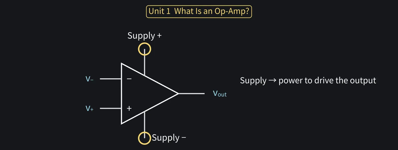
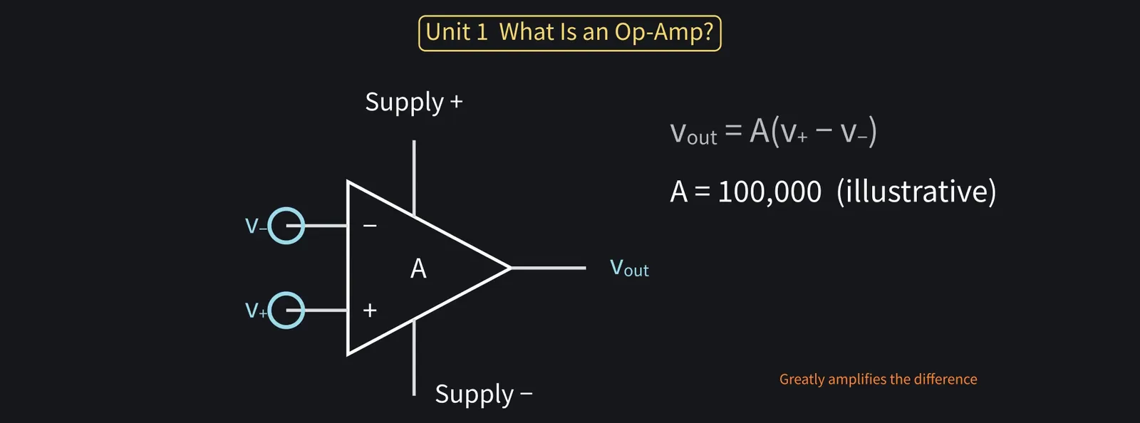
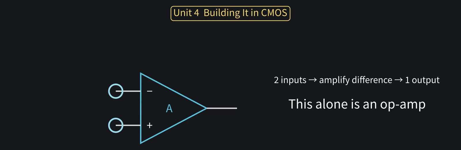
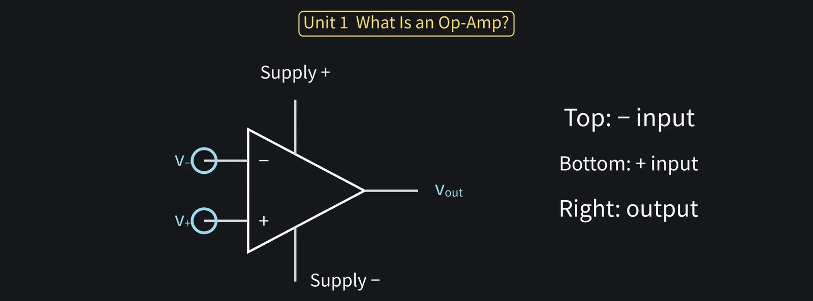
The symbol is this triangle. Two inputs, plus and minus, one output, and power terminals.

Illustration: The symbol is this triangle. Two inputs, plus and minus, one output, and power terminals.
Figure 5

Shikoku Metan

Schematics often omit the supply, but the output's power comes from it.

Illustration: Schematics often omit the supply, but the output's power comes from it.
Figure 6

Shikoku Metan

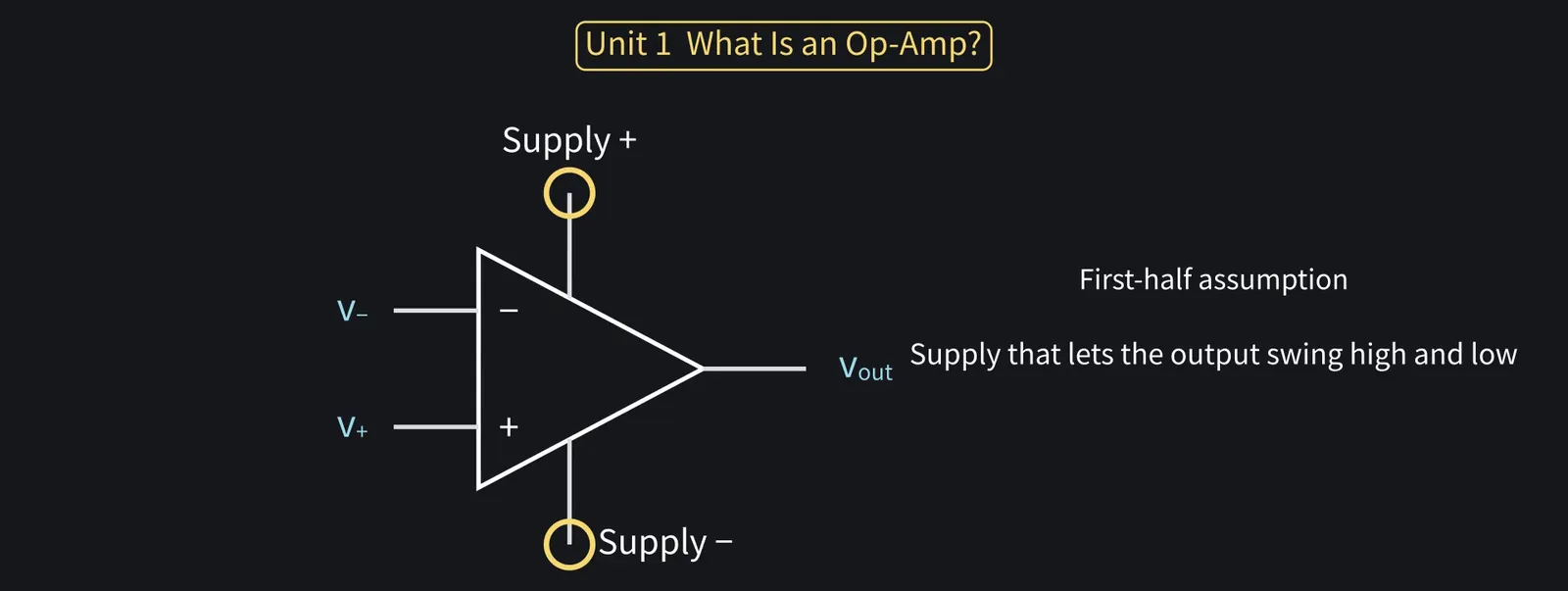
In the first half, assume a supply that lets the output swing high or low freely.

Illustration: In the first half, assume a supply that lets the output swing high or low freely.
Figure 7

Shikoku Metan

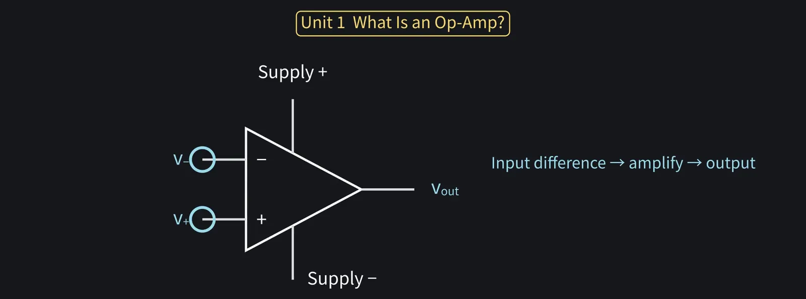
It does one thing: it amplifies the voltage difference between the plus and minus inputs.

Illustration: It does one thing: it amplifies the voltage difference between the plus and minus inputs.
Figure 8

ZundamonQuestion

Only the difference, nanoda? What if both inputs rise by 1 V?
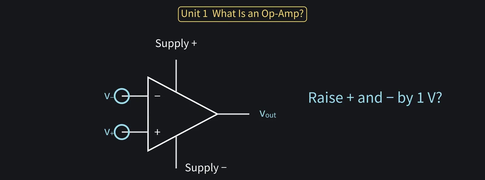
Illustration: Only the difference, nanoda? What if both inputs rise by 1 V?
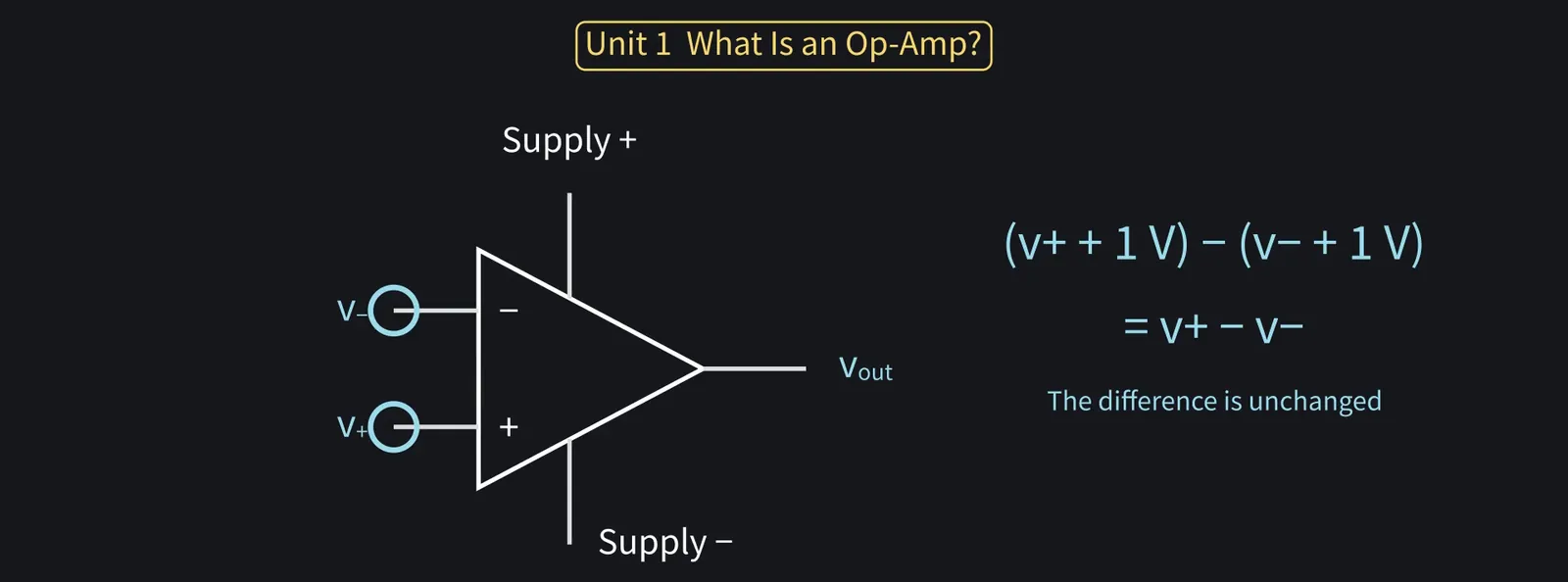
Figure 9

Shikoku Metan

The difference doesn't change, so ideally neither does the output.

Illustration: The difference doesn't change, so ideally neither does the output.
Figure 10

Shikoku Metan

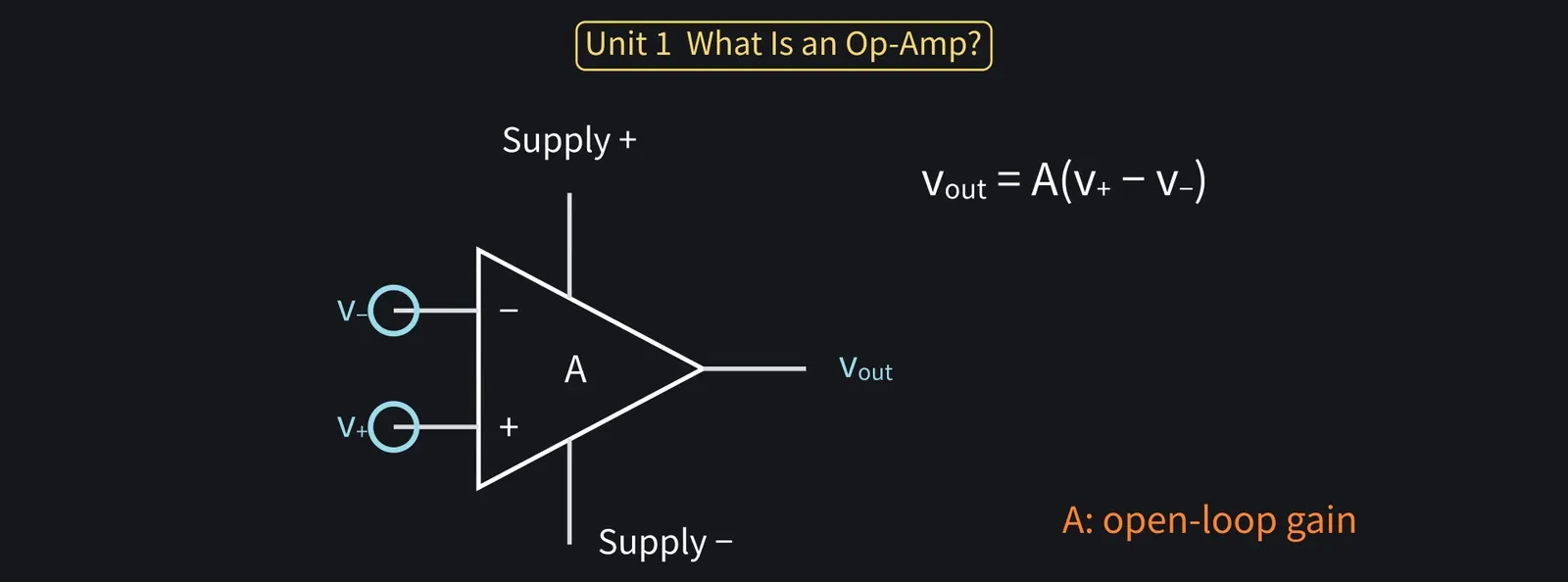
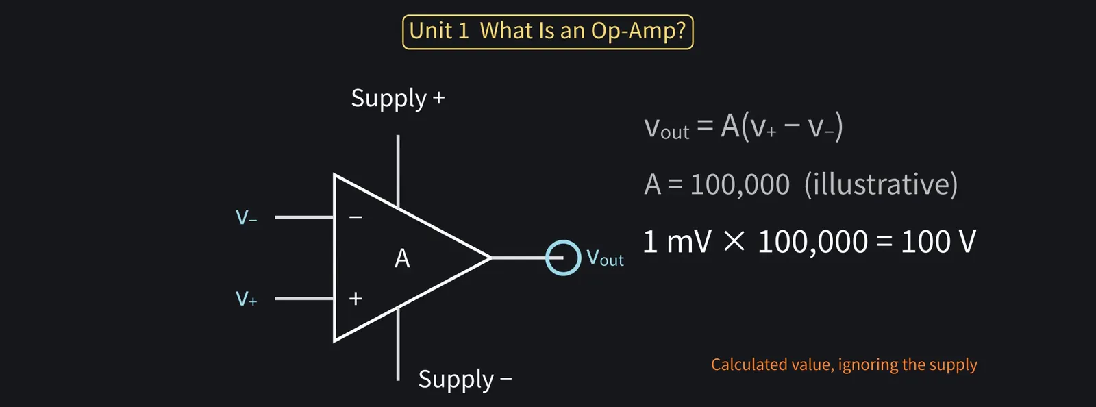
As an equation: vout = A(v+ − v−). A is called the open-loop gain.

Illustration: As an equation: vout = A(v+ − v−). A is called the open-loop gain.
Figure 11

Shikoku Metan

This A is huge. General-purpose parts often exceed 100,000.

Illustration: This A is huge. General-purpose parts often exceed 100,000.
Figure 12

Zundamon

With 100,000, a gain of 10 is a piece of cake, nanoda!
Shikoku Metan

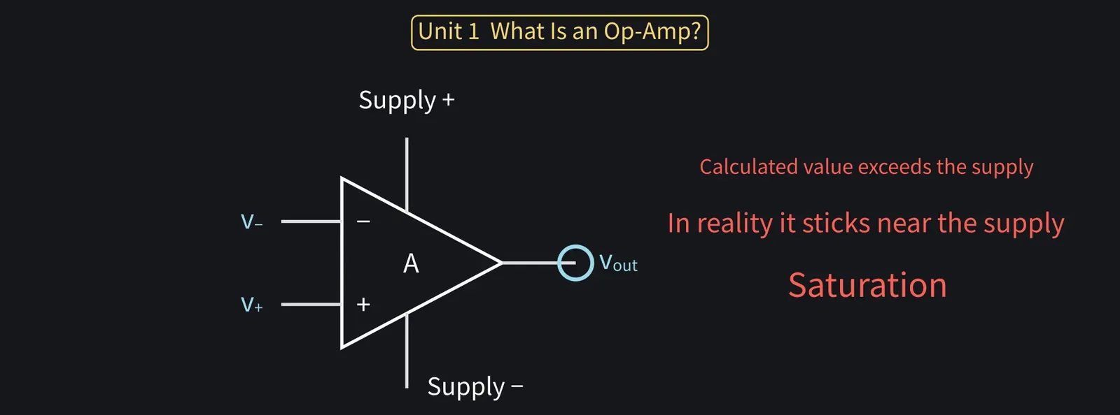
Even a 1 mV input difference would give 100 V at the output on paper, far above the supply voltage.

Illustration: Even a 1 mV input difference would give 100 V at the output on paper, far above the supply voltage.
Figure 13

Shikoku Metan

In reality, the output sticks near the supply. This is called saturation.

Illustration: In reality, the output sticks near the supply. This is called saturation.
Figure 14

Shikoku Metan

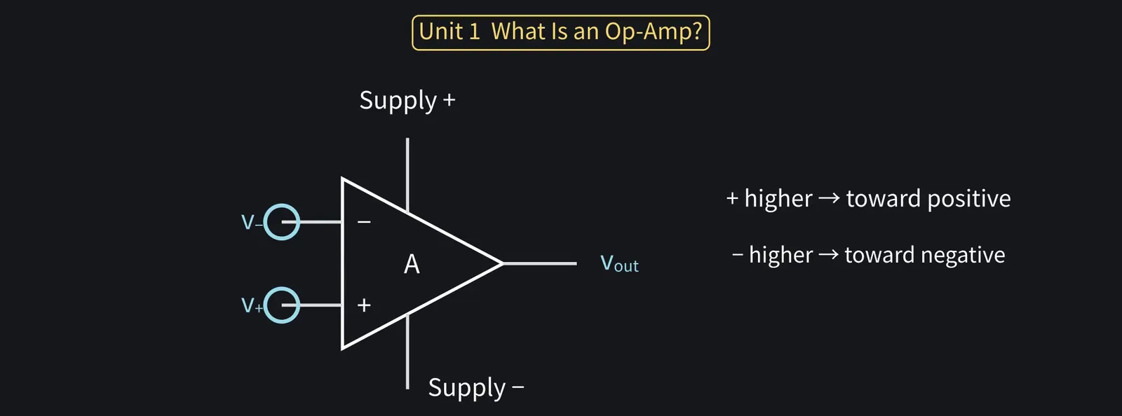
As is, it can only tell which input is higher.

Illustration: As is, it can only tell which input is higher.
Figure 15

Zundamon

So all it can do is amplify by 100,000? That's hard to use, nanoda...

Zundamon: Then why is such a hard-to-use part used everywhere, nanoda?
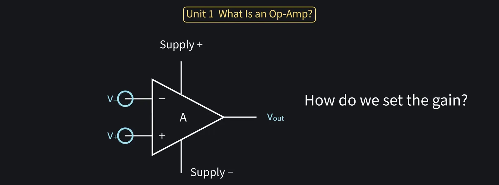
Illustration: Then why is such a hard-to-use part used everywhere, nanoda?
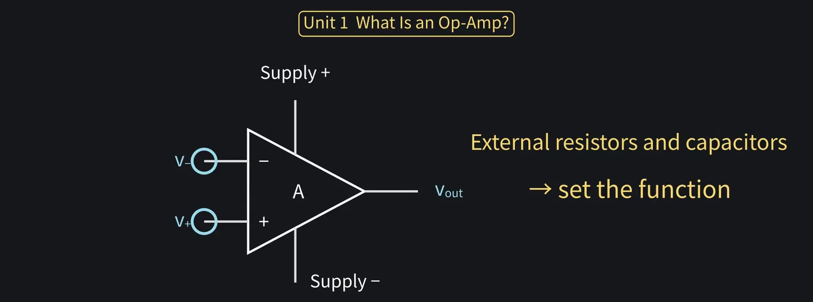
Figure 16

Shikoku Metan

Good question. External resistors and capacitors let you set its function freely.

Illustration: Good question. External resistors and capacitors let you set its function freely.
Figure 17

Shikoku Metan

Unit 1 recap: an op-amp hugely amplifies the input difference. Alone, it saturates.

Illustration: Unit 1 recap: an op-amp hugely amplifies the input difference. Alone, it saturates.
Figure 18

3Negative feedback and the virtual short: two rules

Shikoku Metan

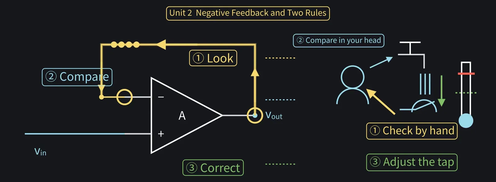
The trick is to send the output back to the input: feedback.

Zundamon

I know feedback, nanoda! Look at the result and use it next time.
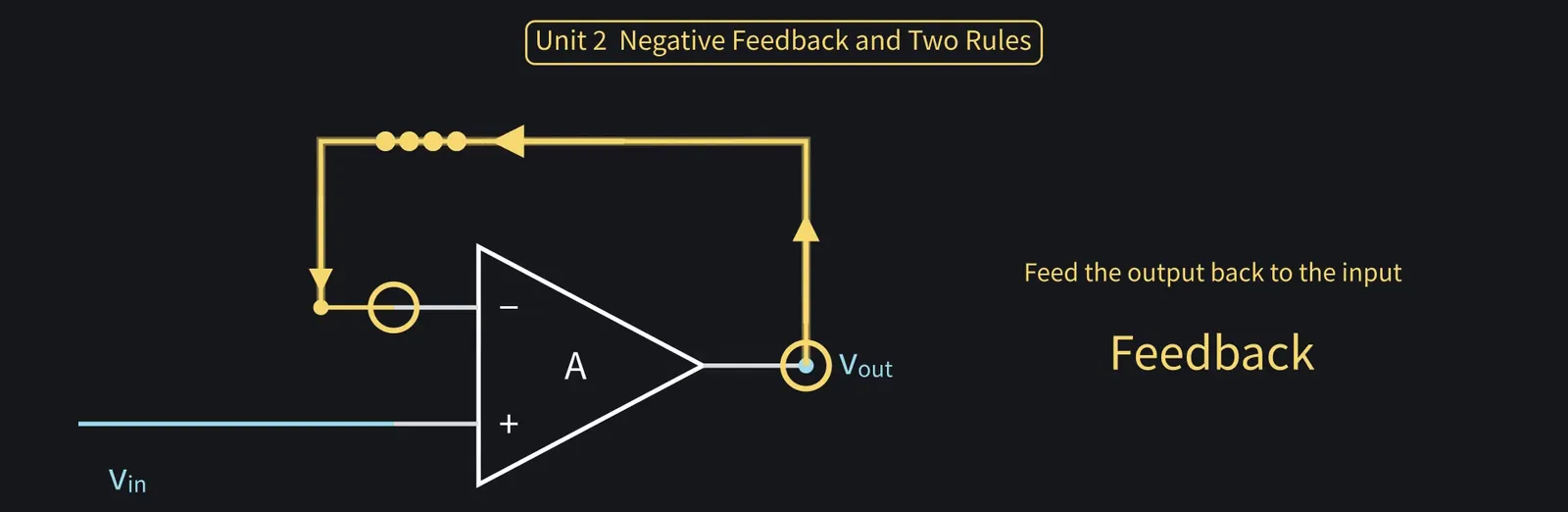
Illustration: I know feedback, nanoda! Look at the result and use it next time.
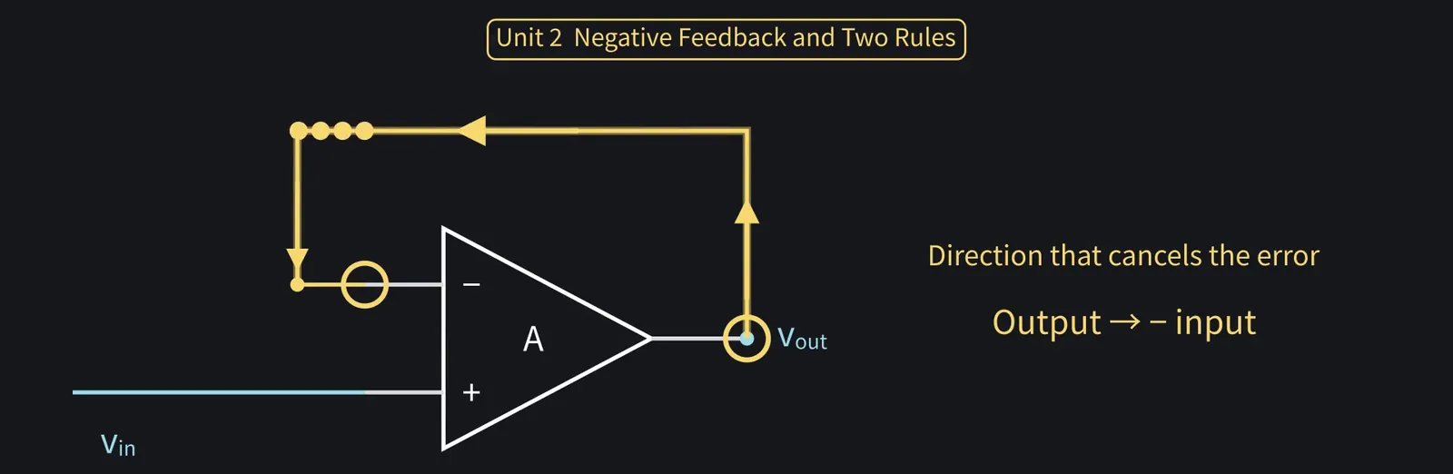
Figure 19

Shikoku Metan

Feeding back to cancel the error is negative feedback: output to the − input.

Illustration: Feeding back to cancel the error is negative feedback: output to the − input.
Figure 20

Shikoku Metan

Like testing shower water with your hand and adding cold if it's hot. Same idea.

Illustration: Like testing shower water with your hand and adding cold if it's hot. Same idea.
Figure 21

Zundamon

Check the temperature, adjust to fix the error, nanoda! I do that every morning!
Shikoku Metan

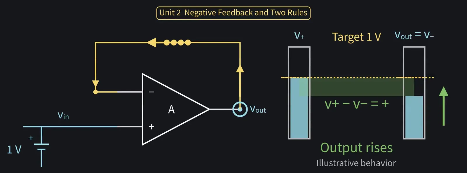
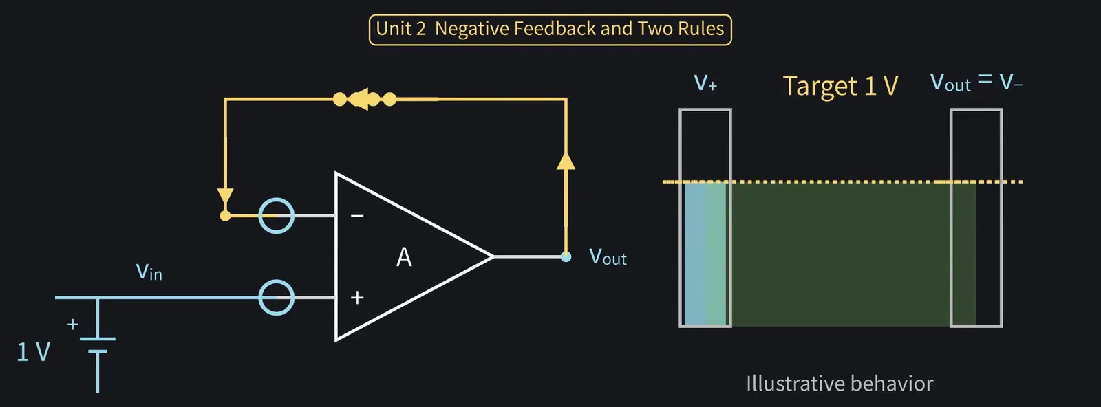
Let's try the simplest form. 1 V at the + input. Output wired straight to the − input.

Illustration: Let's try the simplest form. 1 V at the + input. Output wired straight to the − input.
Figure 22

ZundamonQuestion

Won't feeding the output back go round and round and run wild, nanoda?
Shikoku Metan

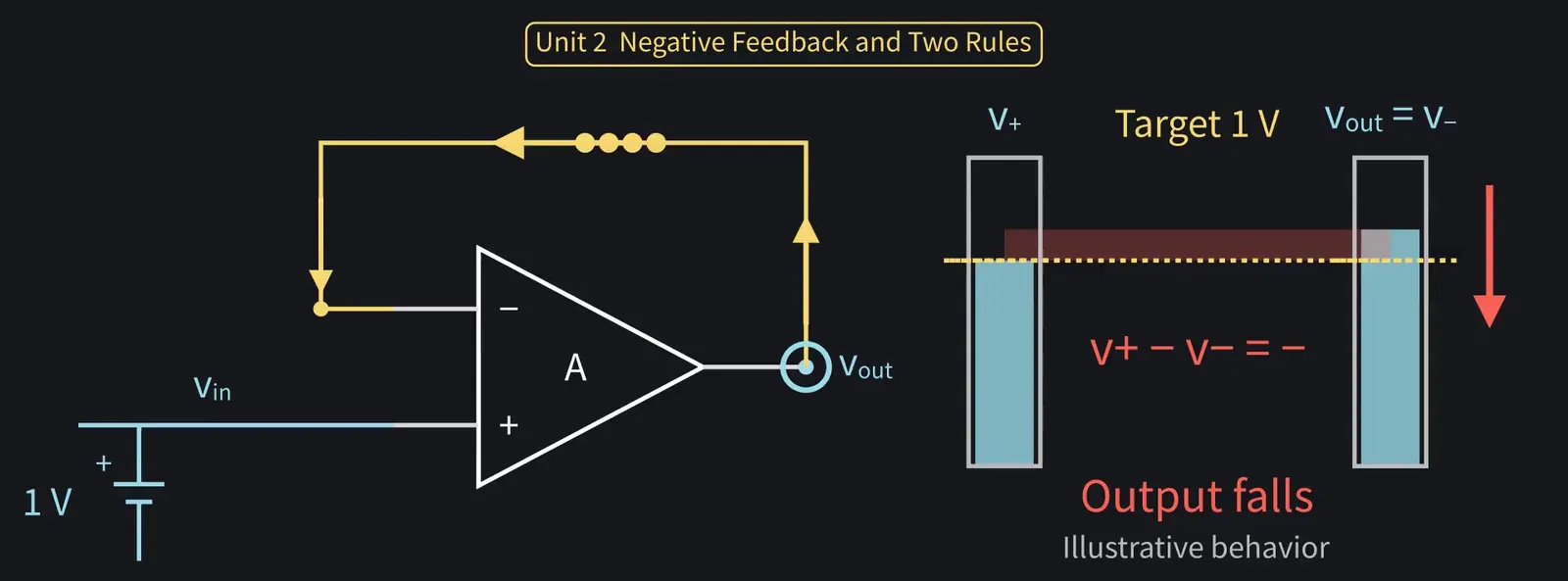
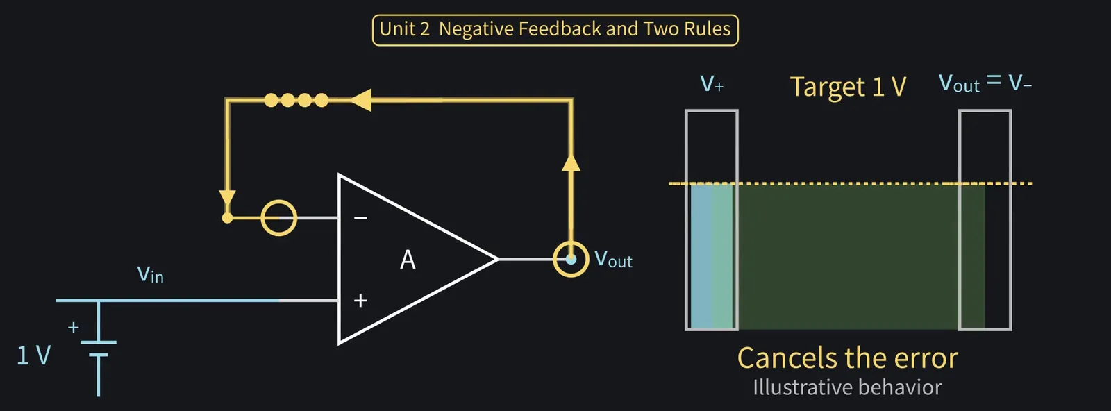
Fed to the − input, it works to cancel the error. Let's follow it step by step.

Illustration: Fed to the − input, it works to cancel the error. Let's follow it step by step.
Figure 23

Shikoku Metan

If the output is below 1 V, the difference v+ − v− is positive, so the output rises.

Illustration: If the output is below 1 V, the difference v+ − v− is positive, so the output rises.
Figure 24

Shikoku Metan

If it overshoots above 1 V, the difference goes negative, and the output falls.

Illustration: If it overshoots above 1 V, the difference goes negative, and the output falls.
Figure 25

Zundamon

Too high or too low, it gets pushed back, and settles at 1 V, nanoda!
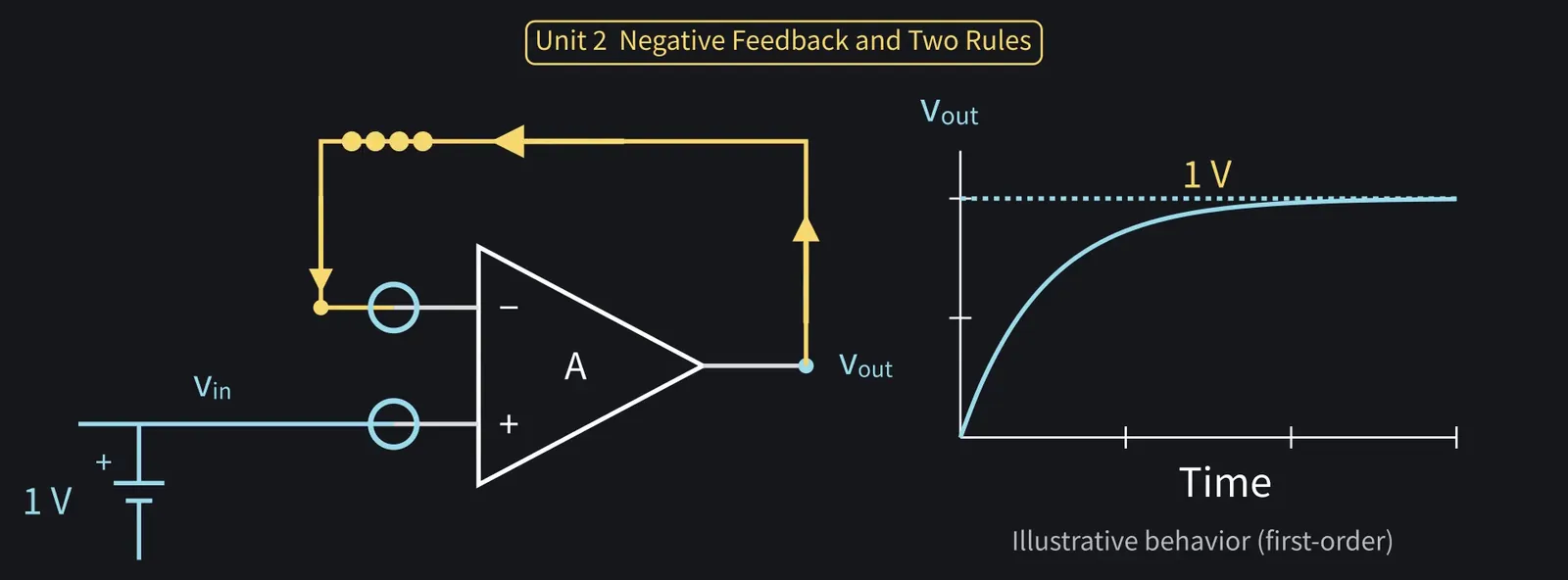
Illustration: Too high or too low, it gets pushed back, and settles at 1 V, nanoda!
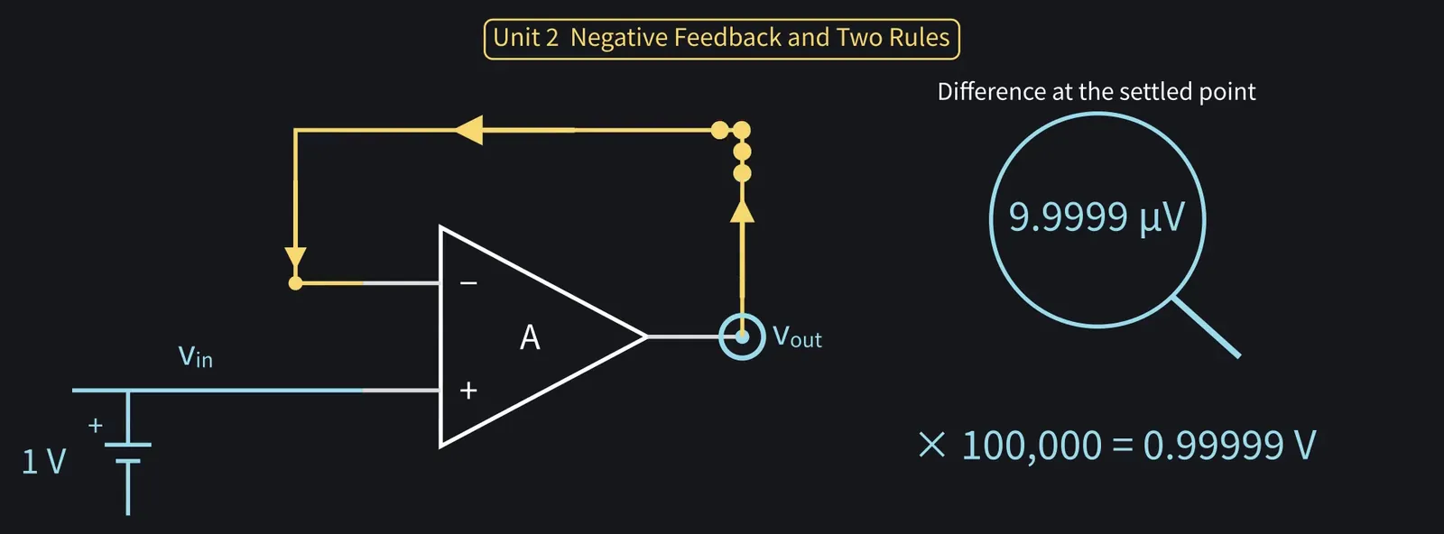
Figure 26

Shikoku Metan

At that point the difference is only 1 V÷100,000, about 10 µV. Multiply it back by 100,000 and you get the 1 V output.

Illustration: At that point the difference is only 1 V ÷ 100,000, about 10 µV. Multiply it back by 100,000 and you get the 1 V output.
Figure 27

Shikoku Metan

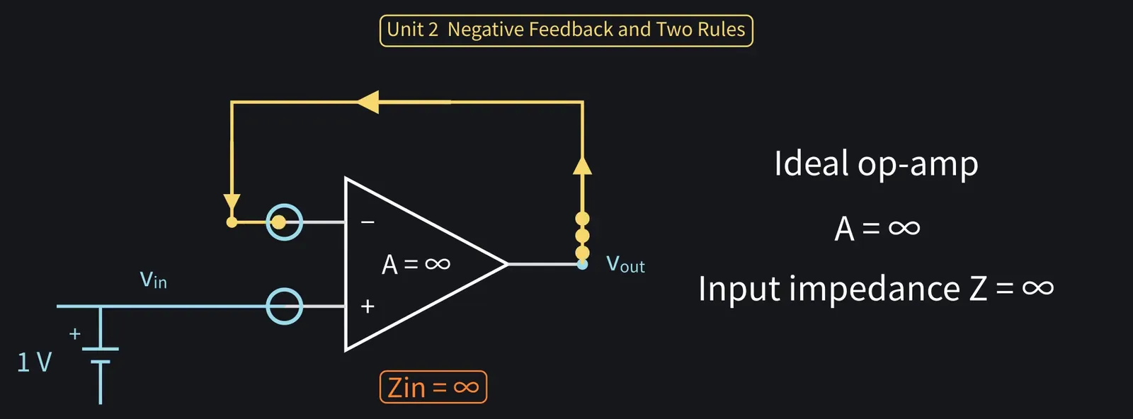
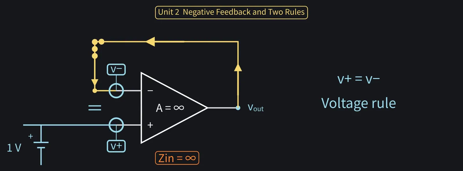
Now consider an ideal op-amp: gain A is infinite, input impedance is infinite too.

Illustration: Now consider an ideal op-amp: gain A is infinite, input impedance is infinite too.
Figure 28

Shikoku Metan

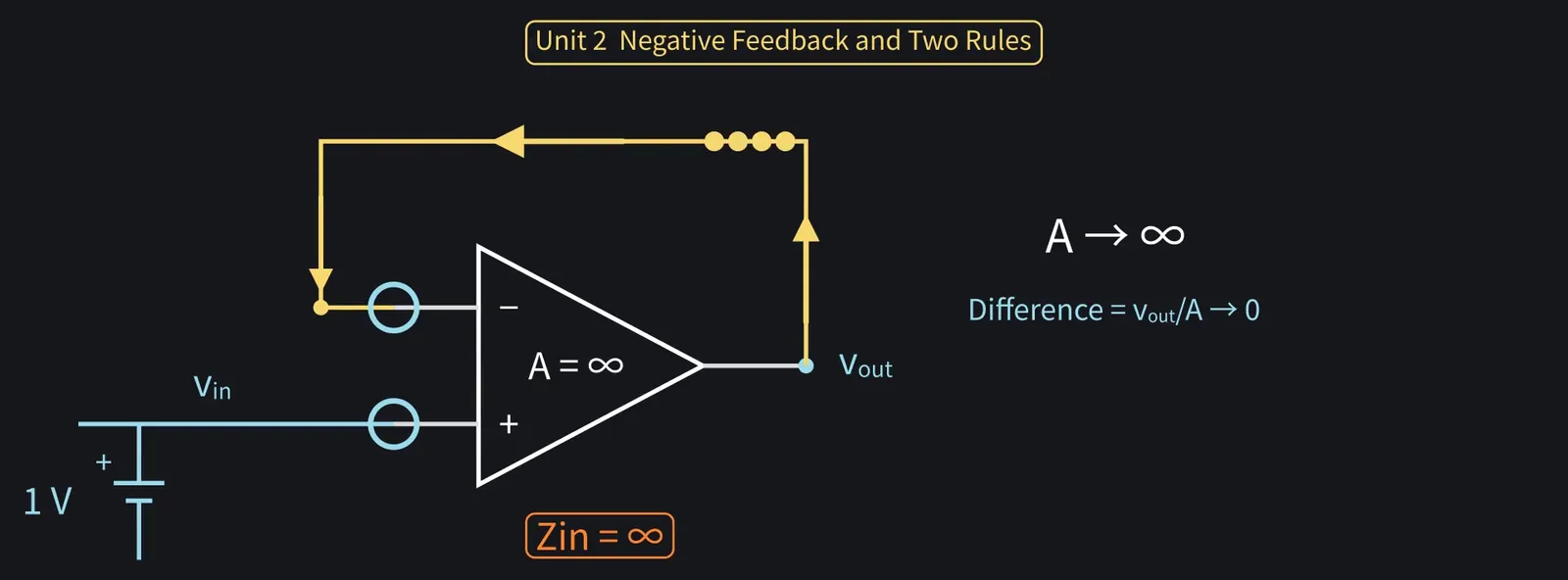
The output is finite, so the input difference is vout/A. With A infinite, it's 0.

Illustration: The output is finite, so the input difference is vout/A. With A infinite, it's 0.
Figure 29

Shikoku Metan

With negative feedback, the + and − voltages are equal. That's rule one, the voltage rule.

Illustration: With negative feedback, the + and − voltages are equal. That's rule one, the voltage rule.
Figure 30

Shikoku Metan

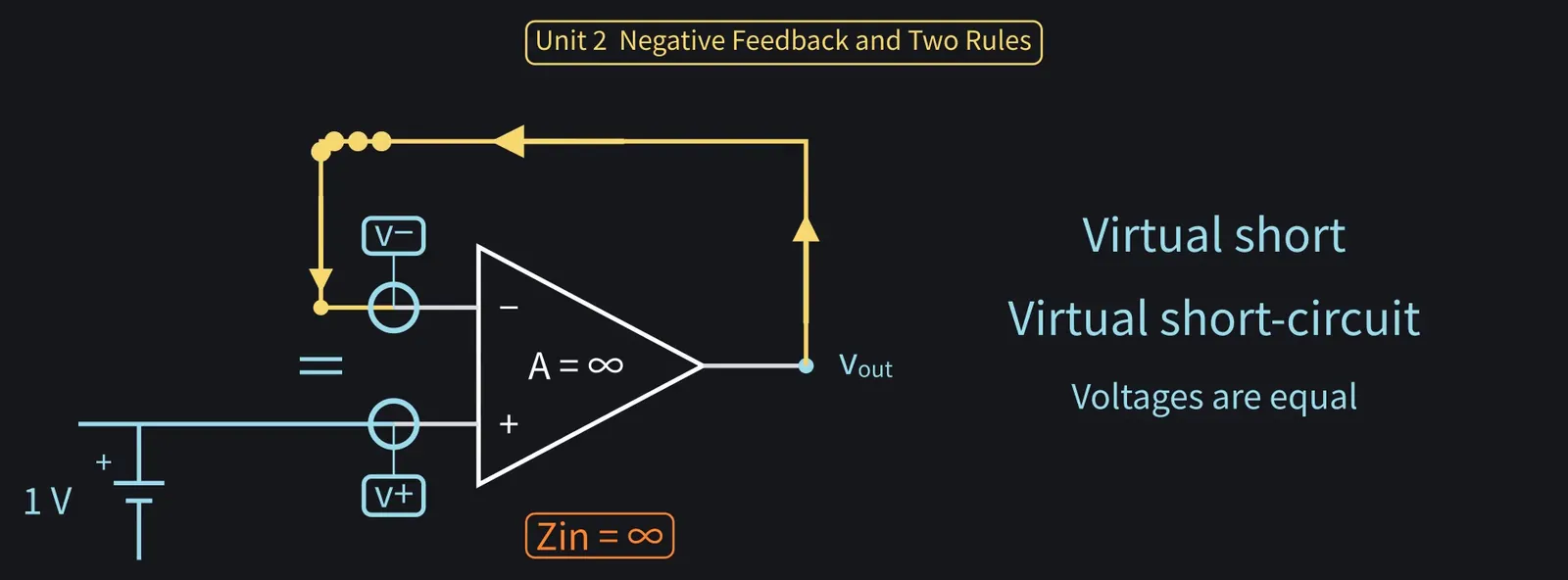
This state is called a virtual short.

Illustration: This state is called a virtual short.
Figure 31

ZundamonQuestion

A short means joining two points with a wire, nanoda? Are the inputs connected?
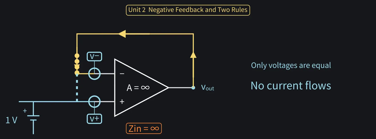
Illustration: A short means joining two points with a wire, nanoda? Are the inputs connected?
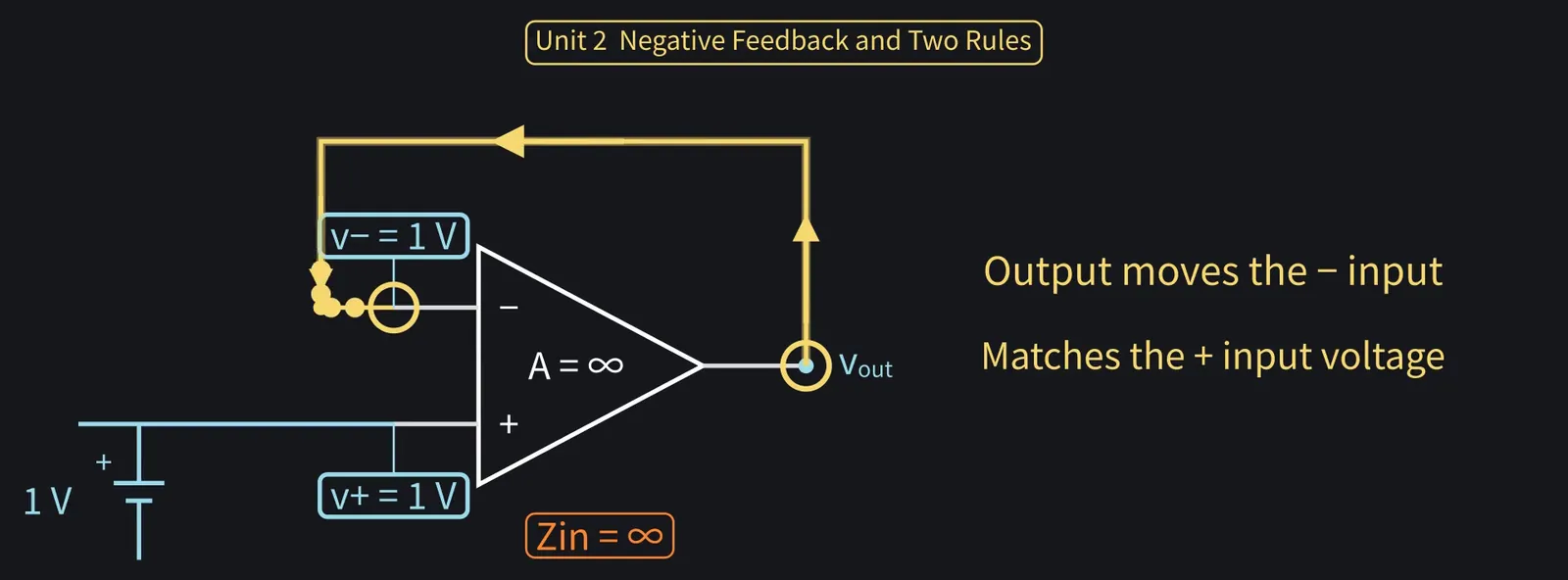
Figure 32

Shikoku Metan

The voltages are equal, as if wired together. But no current flows between the two.

Shikoku Metan: Instead of a wire, the output moves the − input to match: a "virtual" short.

Illustration: Instead of a wire, the output moves the − input to match: a "virtual" short.
Figure 33

Zundamon

Not a real wire, just an apparent short made by negative feedback, nanoda!
Shikoku Metan

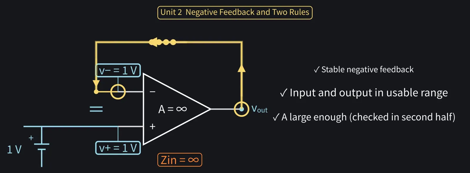
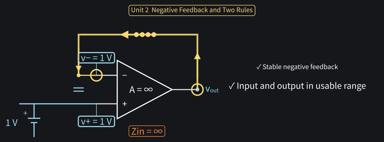
This assumes stable feedback, with input and output within the usable voltage range.

Illustration: This assumes stable feedback, with input and output within the usable voltage range.
Figure 34

Shikoku Metan

A real A is finite, but if A is large and the feedback is strong, the approximation holds. We'll check this in the second half.

Illustration: A real A is finite, but if A is large and the feedback is strong, the approximation holds. We'll check this in the second half.
Figure 35

Shikoku Metan

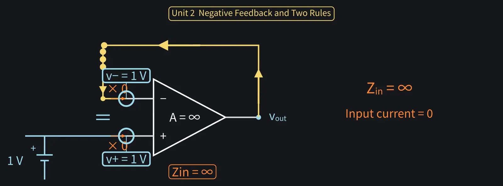
Rule two, the current rule: input impedance is infinite, so no current enters the inputs.

Illustration: Rule two, the current rule: input impedance is infinite, so no current enters the inputs.
Figure 36

ZundamonQuestion

Is it negative feedback that keeps current out of the input too, nanoda?
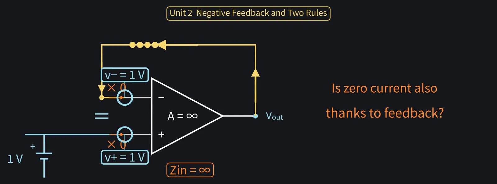
Illustration: Is it negative feedback that keeps current out of the input too, nanoda?

Figure 37

Shikoku Metan

No, that's a property of the input impedance. It holds with or without feedback.

Shikoku Metan: Unit 2 recap: with feedback, + and − voltages are equal and input current is 0.

Illustration: Unit 2 recap: with feedback, + and − voltages are equal and input current is 0.
Figure 38

Zundamon

Only two rules, nanoda! I want to solve circuits with them!

4Voltage followers and non-inverting amplifiers

Shikoku Metan

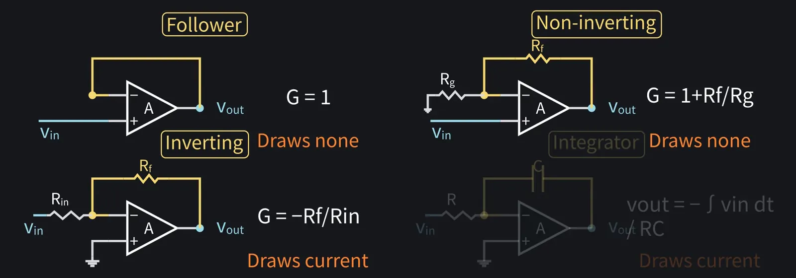
Now, four common circuits: follower, non-inverting, inverting, and integrator.

Illustration: Now, four common circuits: follower, non-inverting, inverting, and integrator.
Figure 39

Shikoku Metan

Same method every time: use the virtual short to fix the − input voltage, then write KCL with zero input current.

Illustration: Same method every time: use the virtual short to fix the − input voltage, then write KCL with zero input current.
Figure 40

Zundamon

If one procedure solves them all, there's less to memorize, nanoda!
Shikoku Metan

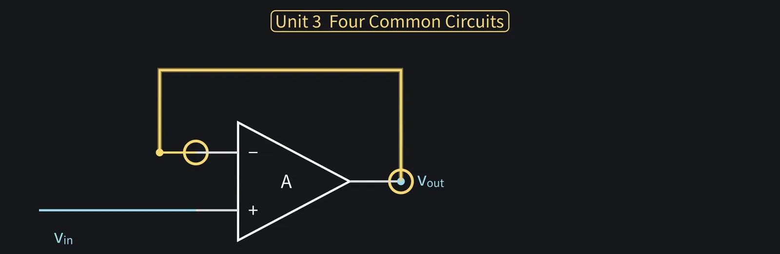
First is the circuit we just saw. It's called a voltage follower.

Illustration: First is the circuit we just saw. It's called a voltage follower.
Figure 41

Shikoku Metan

Let's derive it. The − input is wired to the output, so v− = vout.

Shikoku Metan: By the voltage rule, v− = v+ = vin. So vout=vin, and the gain is 1.

ZundamonQuestion

If it just outputs the same voltage, what's the point of connecting it, nanoda?
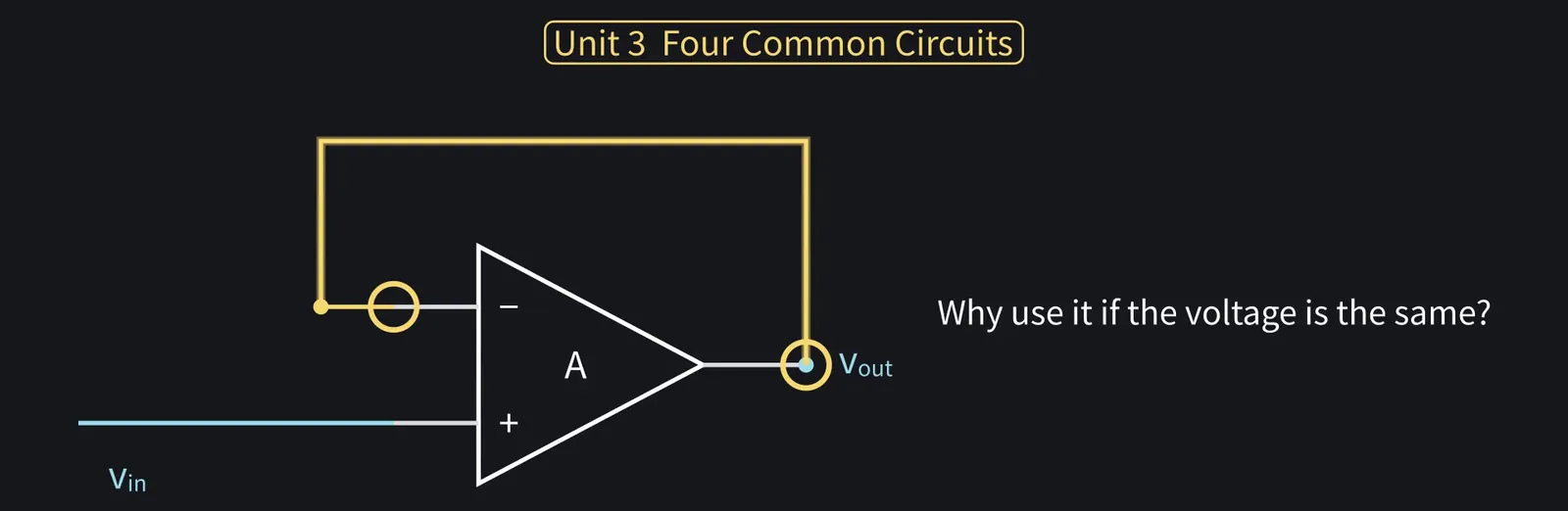
Illustration: If it just outputs the same voltage, what's the point of connecting it, nanoda?
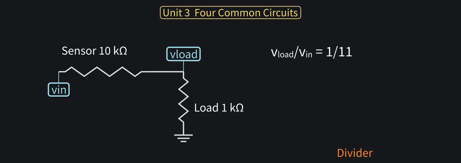
Figure 42

Shikoku Metan

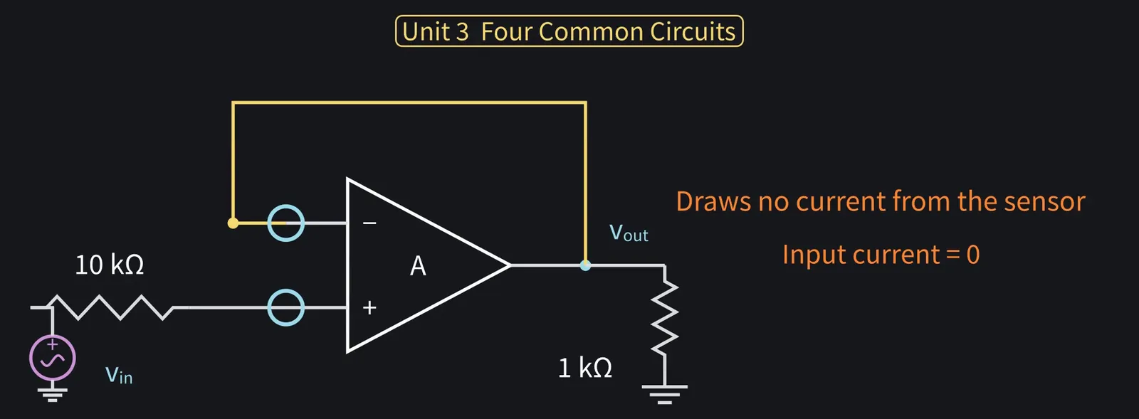
Wire a 1 kΩ load straight to a sensor with 10 kΩ internal resistance, and the voltage divider leaves only 1/11 of the signal.

Illustration: Wire a 1 kΩ load straight to a sensor with 10 kΩ internal resistance, and the voltage divider leaves only 1/11 of the signal.
Figure 43

Shikoku Metan

With a follower in between, the current rule means it draws no current from the sensor.

Illustration: With a follower in between, the current rule means it draws no current from the sensor.
Figure 44

Shikoku Metan

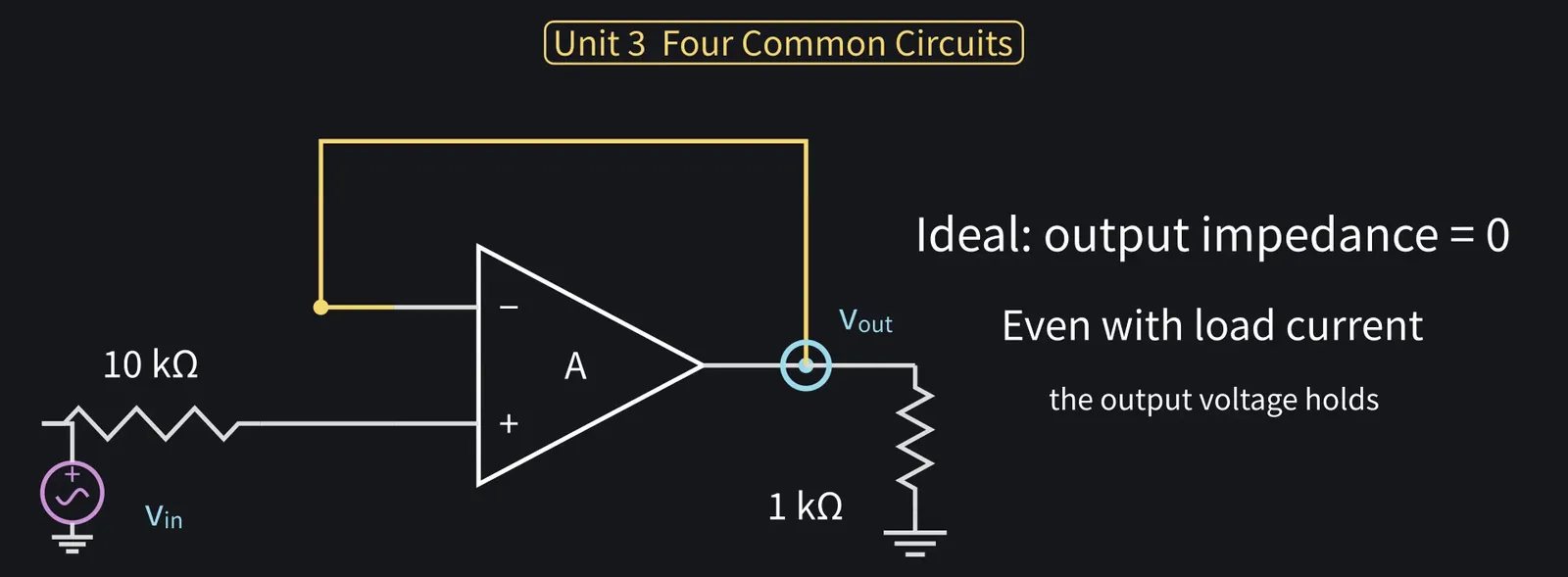
And ideally output impedance is 0, so load current doesn't change the output.

Illustration: And ideally output impedance is 0, so load current doesn't change the output.
Figure 45

Zundamon

Same voltage, and the op-amp does the heavy lifting, nanoda! That's a buffer!
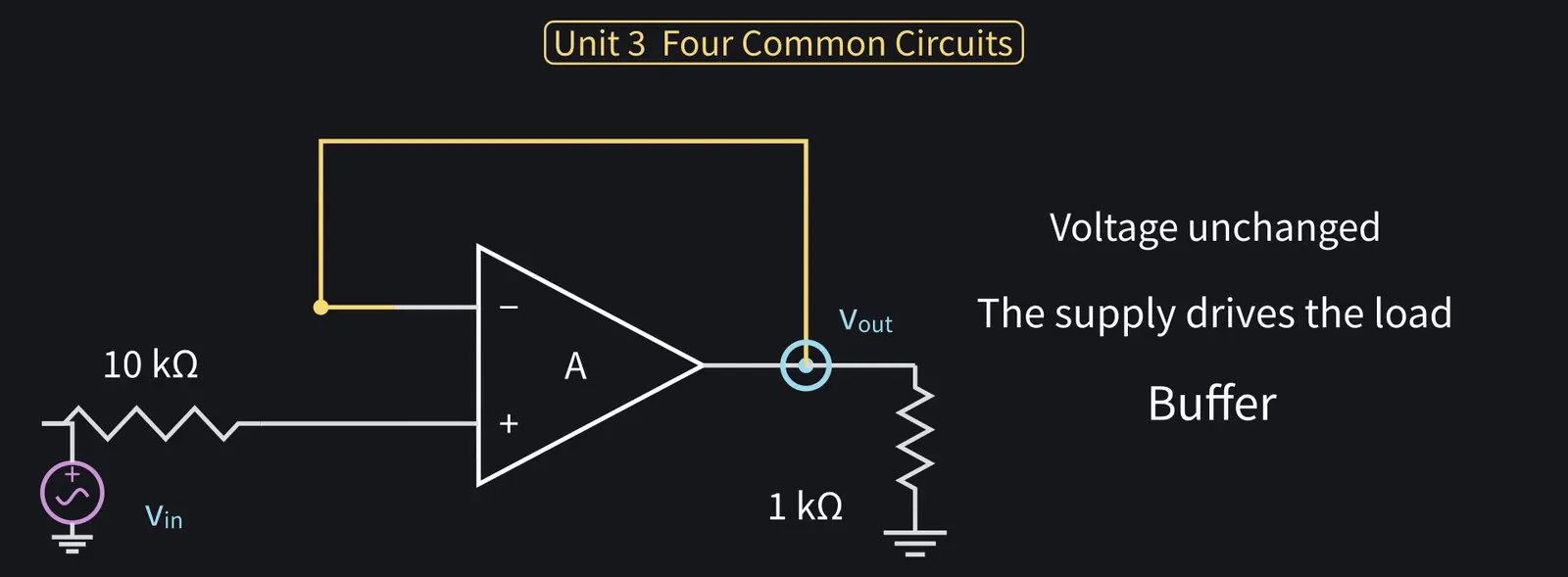
Illustration: Same voltage, and the op-amp does the heavy lifting, nanoda! That's a buffer!
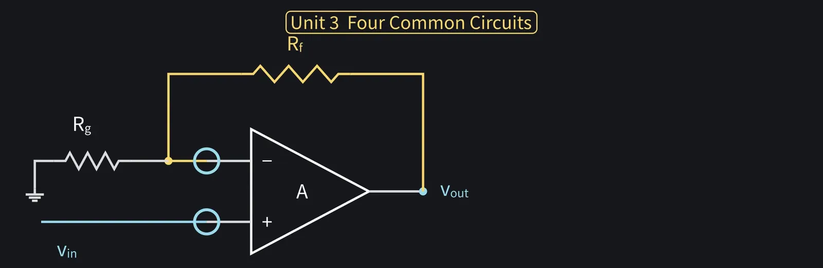
Figure 46

Shikoku Metan

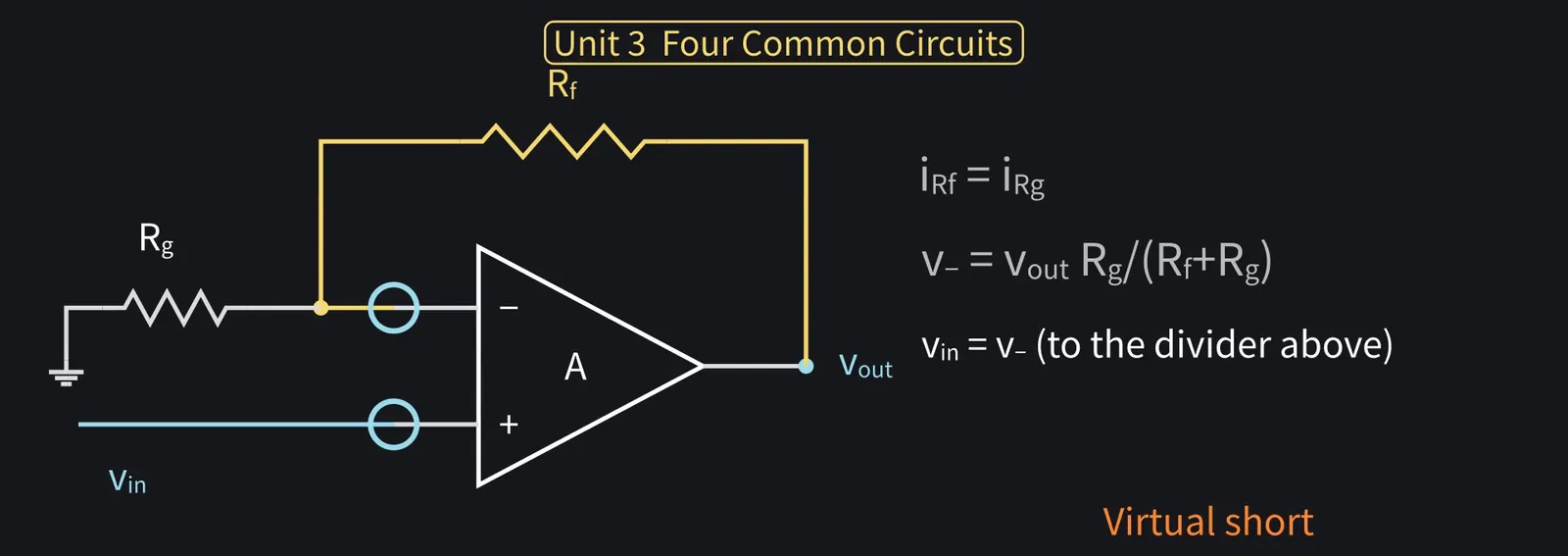
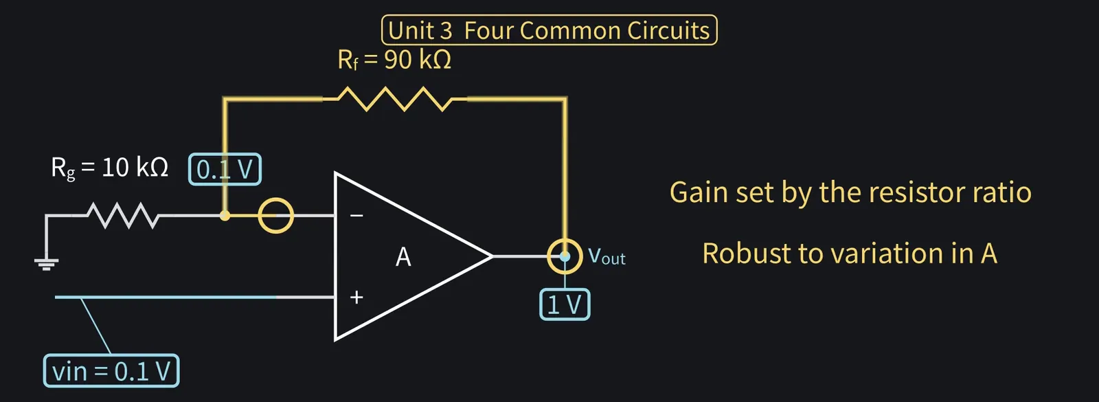
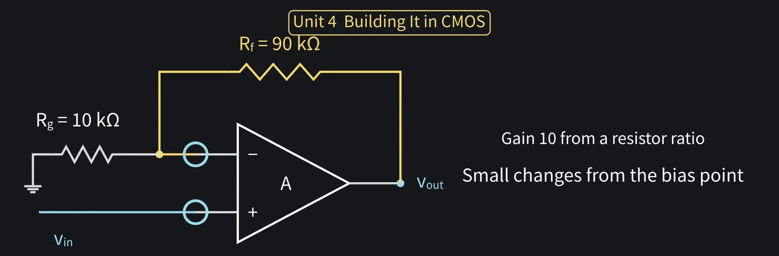
Second, non-inverting. Input to +; Rf and Rg divide the output back to the − input.

Illustration: Second, non-inverting. Input to +; Rf and Rg divide the output back to the − input.
Figure 47

ZundamonQuestion

You shrink the output you worked for and feed it back, nanoda? That amplifies?
Shikoku Metan

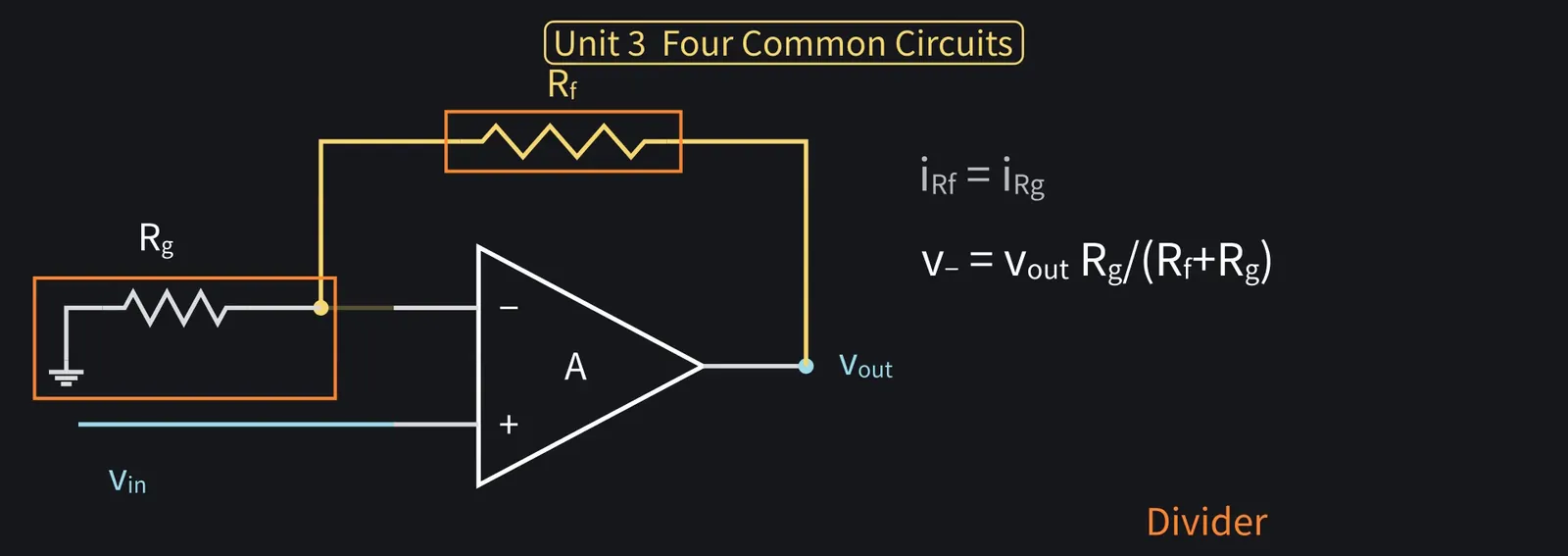
Step by step. No current enters the − input, so Rf and Rg carry the same current.

Shikoku Metan: So they're just in series. The divider gives v− = vout×Rg/(Rf+Rg).

Illustration: So they're just in series. The divider gives v− = vout × Rg/(Rf + Rg).
Figure 48

Shikoku Metan

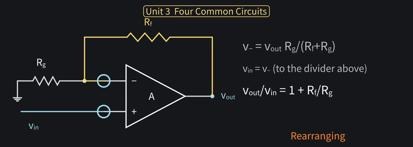
Next, the voltage rule: v− = vin. So vin=vout×Rg/(Rf+Rg).

Illustration: Next, the voltage rule: v− = vin. So vin = vout × Rg/(Rf + Rg).
Figure 49

Shikoku Metan

Rearranging: vout/vin = (Rf+Rg)/Rg=1+Rf/Rg. That's the gain.

Illustration: Rearranging: vout/vin = (Rf + Rg)/Rg = 1 + Rf/Rg. That's the gain.
Figure 50

Zundamon

With Rg=10 kΩ and Rf=90 kΩ, it's 10 times, nanoda! 0.1 V becomes 1 V!
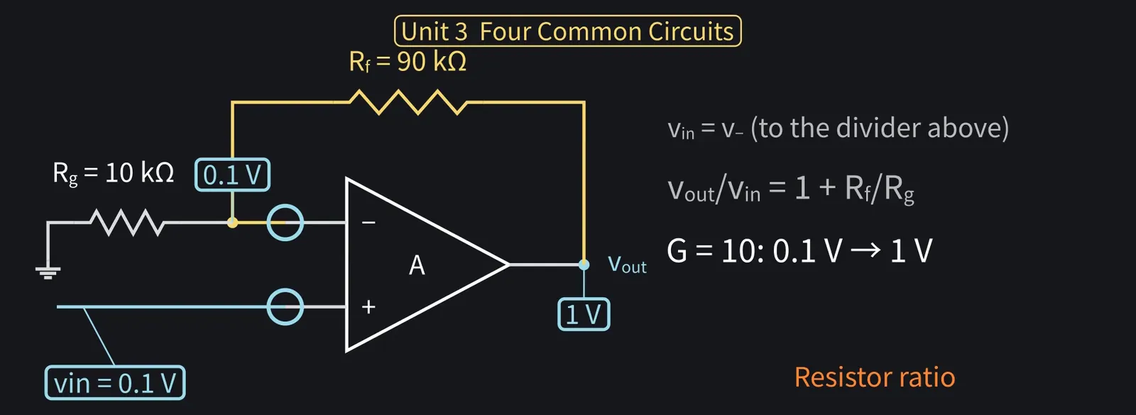
Illustration: With Rg = 10 kΩ and Rf = 90 kΩ, it's 10 times, nanoda! 0.1 V becomes 1 V!
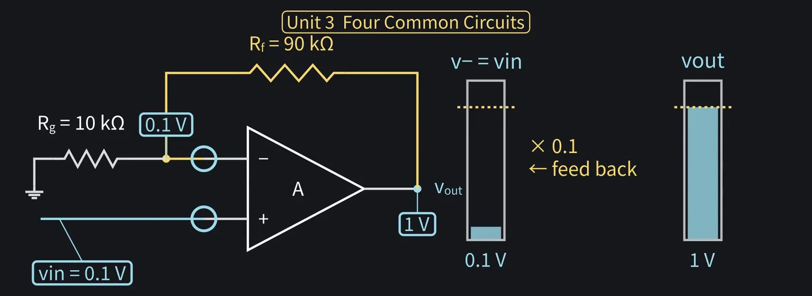
Figure 51

Shikoku Metan

Only one tenth of the output is fed back, and that tenth has to equal the input. So the output ends up 10 times the input.

Illustration: Only one tenth of the output is fed back, and that tenth has to equal the input. So the output ends up 10 times the input.
Figure 52

Shikoku Metan

Even if A varies, gain is set mostly by the resistor ratio. That's feedback's strength.

Illustration: Even if A varies, gain is set mostly by the resistor ratio. That's feedback's strength.
Figure 53

5Inverting amplifiers and integrators

Shikoku Metan

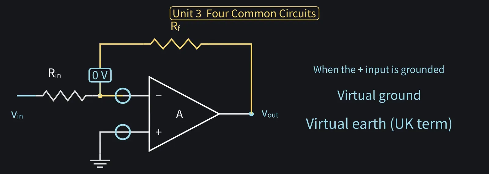
Third, inverting. Ground the + input; Rin and feedback resistor Rf go to the − input.

ZundamonQuestion

This time the − input isn't grounded, nanoda. How is its voltage decided?
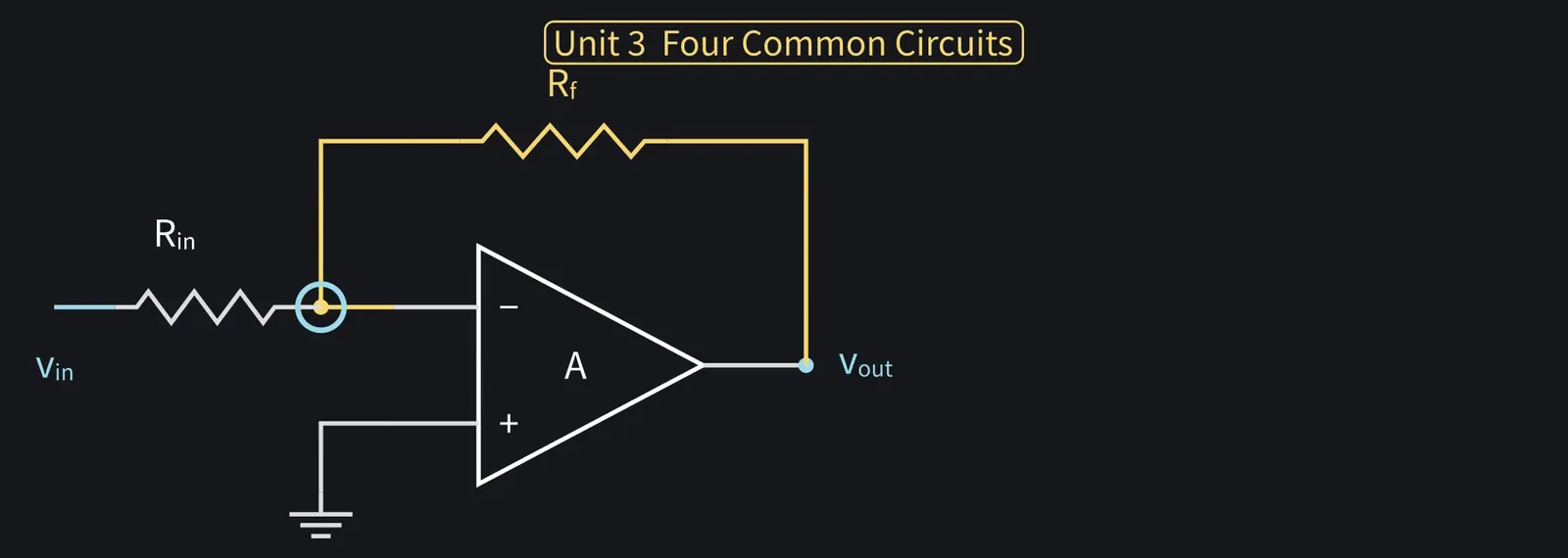
Illustration: This time the − input isn't grounded, nanoda. How is its voltage decided?
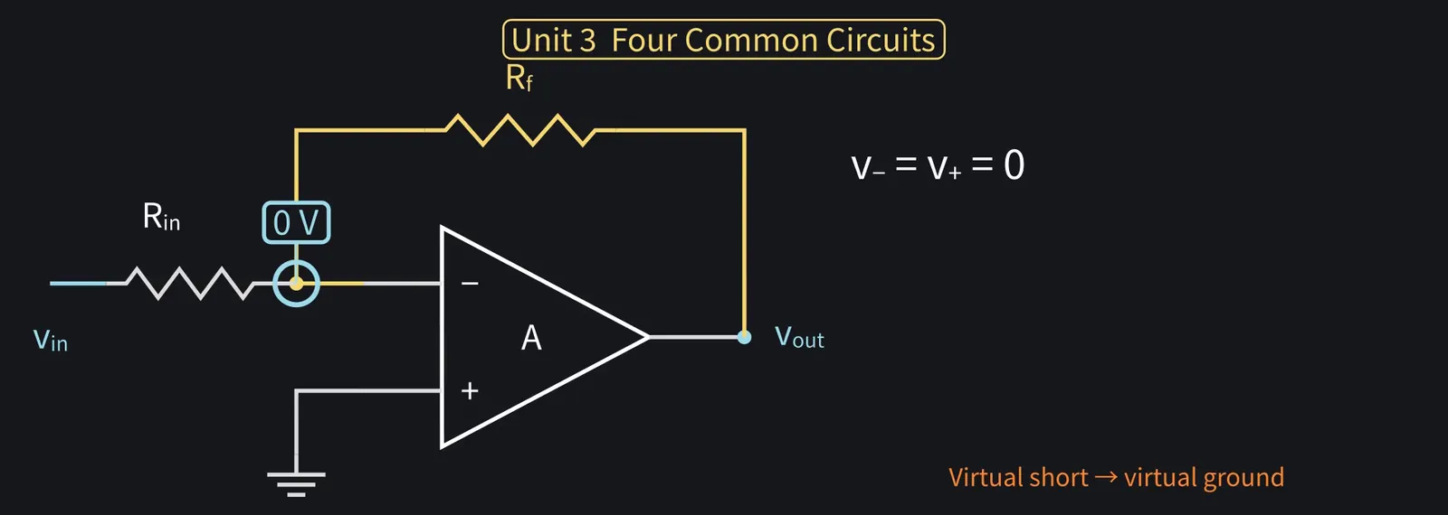
Figure 54

Shikoku Metan

By the virtual short, the − input is 0 V like the + input. Not grounded: virtual ground.

Illustration: By the virtual short, the − input is 0 V like the + input. Not grounded: virtual ground.
Figure 55

Shikoku Metan

It's the virtual short when the + input is grounded. Hence the name.

Illustration: It's the virtual short when the + input is grounded. Hence the name.
Figure 56

Shikoku Metan

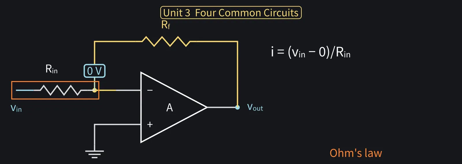
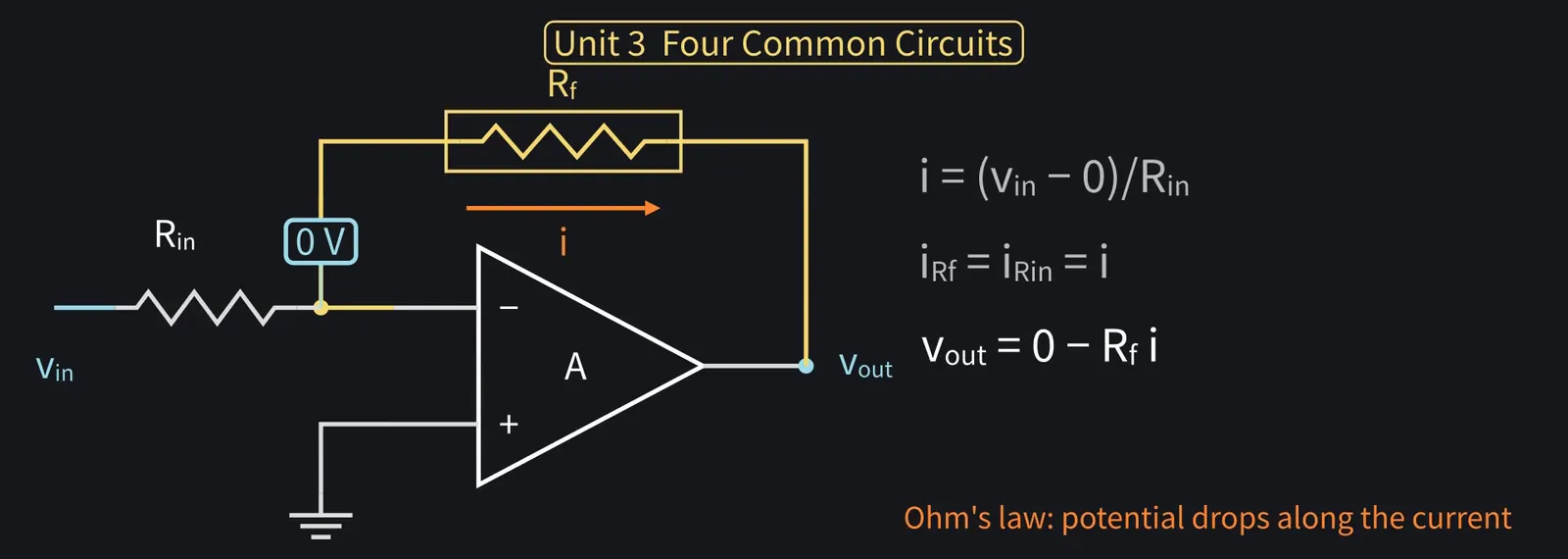
Rin has vin and 0 V across it. By Ohm's law, the current through Rin is i = vin/Rin.

Illustration: Rin has vin and 0 V across it. By Ohm's law, the current through Rin is i = vin/Rin.
Figure 57

Shikoku Metan

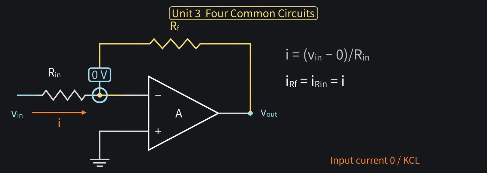
KCL at the − input. Current can't enter it, so the same i flows through Rf.

Illustration: KCL at the − input. Current can't enter it, so the same i flows through Rf.
Figure 58

Shikoku Metan

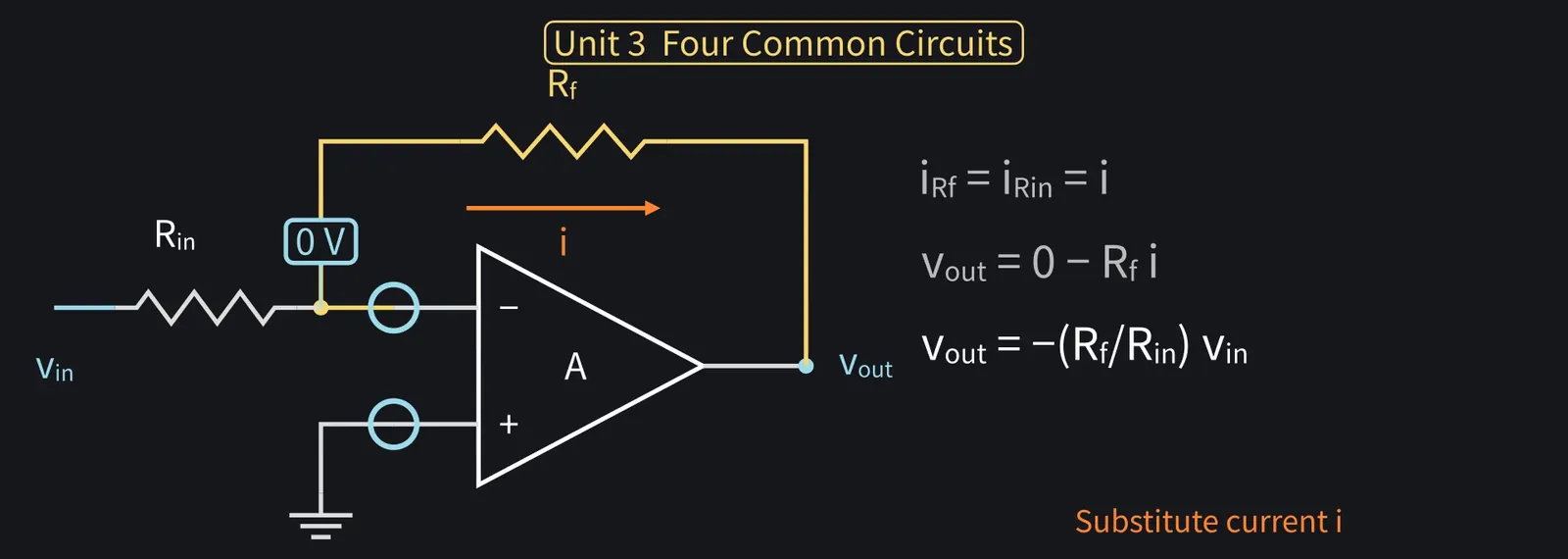
Rf has 0 V on one end and vout on the other. The current i flows from the − input side toward the output, and the potential drops along the current, so vout=0−Rf × i.

Illustration: Rf has 0 V on one end and vout on the other. The current i flows from the − input side toward the output, and the potential drops along the current, so vout = 0 − Rf × i.
Figure 59

Shikoku Metan

Substituting i: vout = −(Rf/Rin)vin. The gain is −Rf/Rin.

Illustration: Substituting i: vout = −(Rf/Rin)vin. The gain is −Rf/Rin.
Figure 60

Zundamon

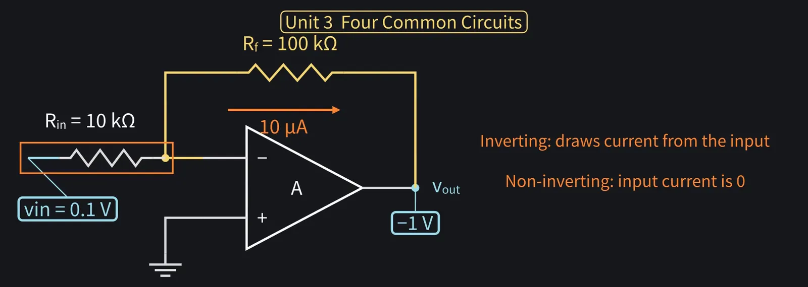
With Rin=10 kΩ, Rf=100 kΩ, 0.1 V in: 10 µA flows, output −1 V, nanoda!
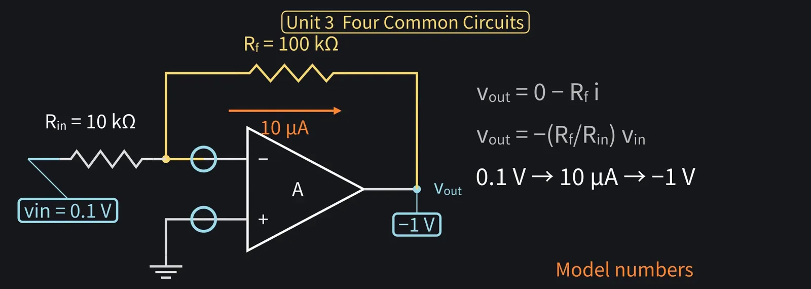
Illustration: With Rin = 10 kΩ, Rf = 100 kΩ, 0.1 V in: 10 µA flows, output −1 V, nanoda!
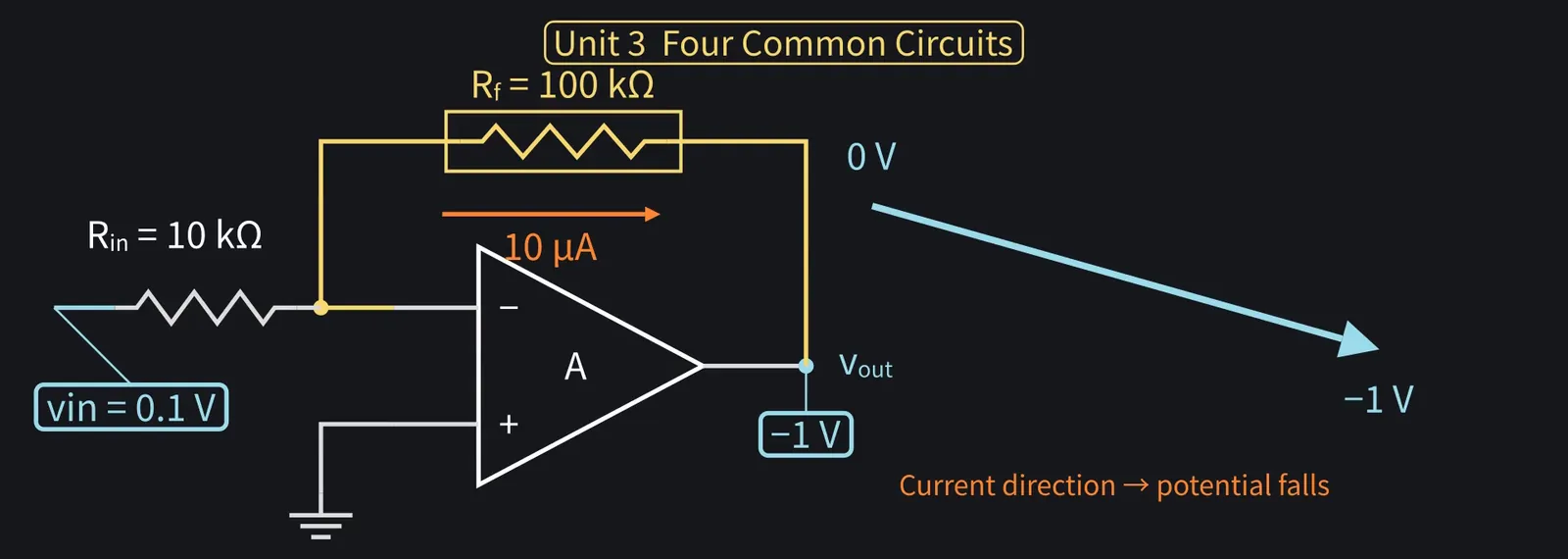
Figure 61

Shikoku Metan

Opposite direction: −10 times. When the input rises, the output falls.

Illustration: Opposite direction: −10 times. When the input rises, the output falls.
Figure 62

Shikoku Metan

This circuit draws current from the input through Rin, unlike the non-inverting one.

Illustration: This circuit draws current from the input through Rin, unlike the non-inverting one.
Figure 63

Shikoku Metan

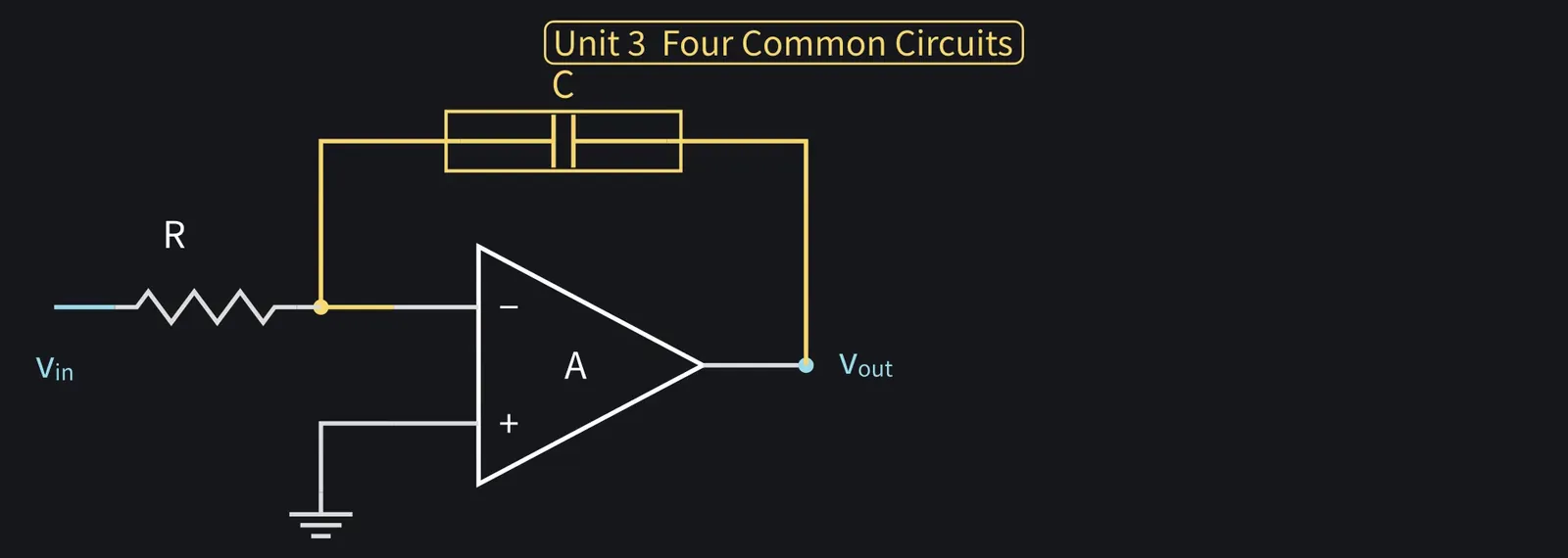
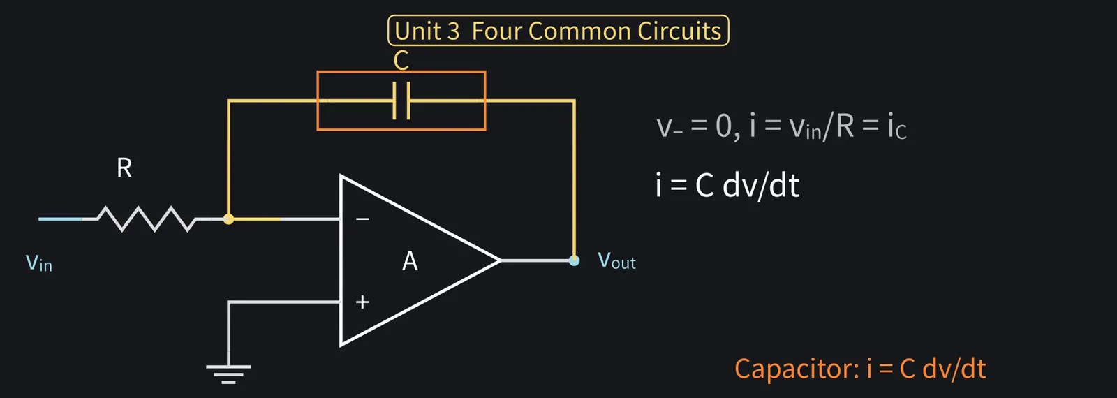
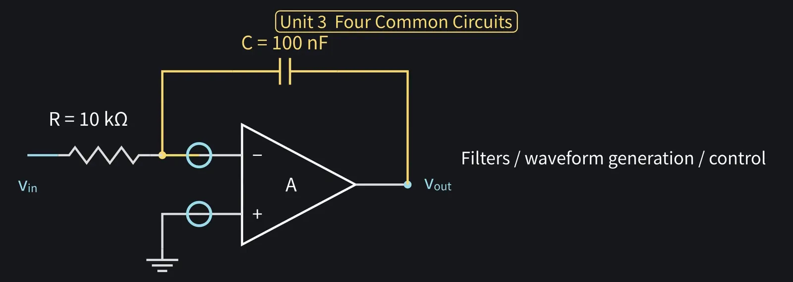
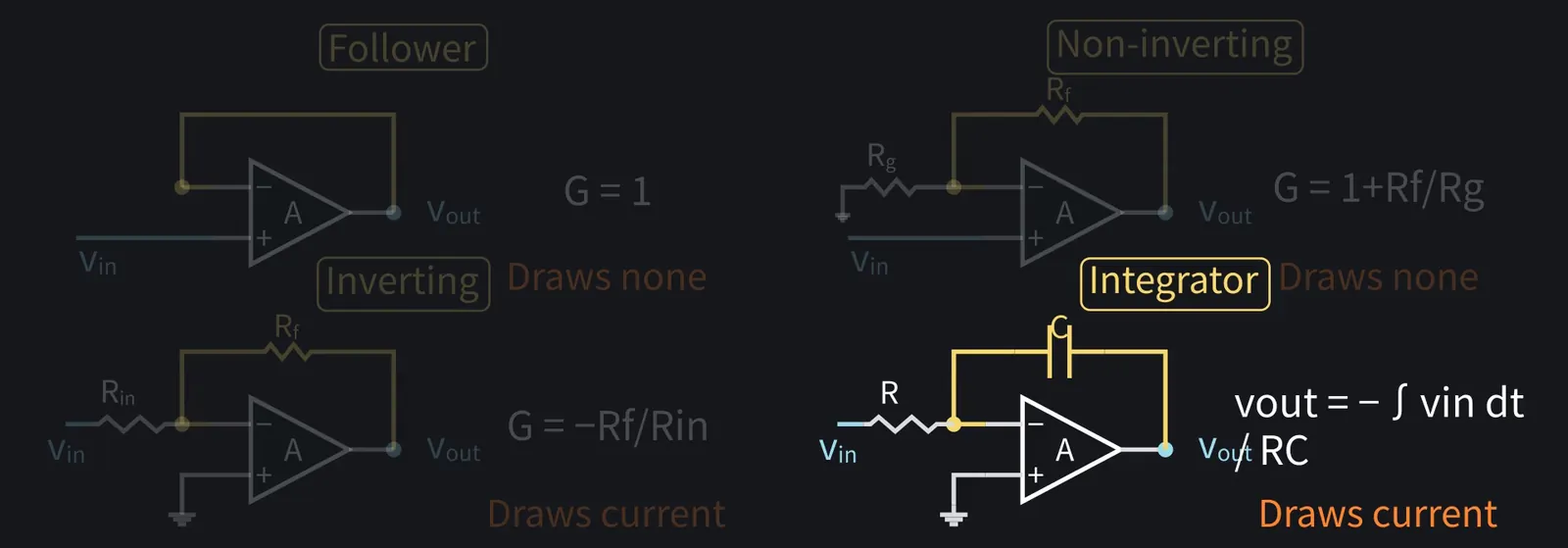
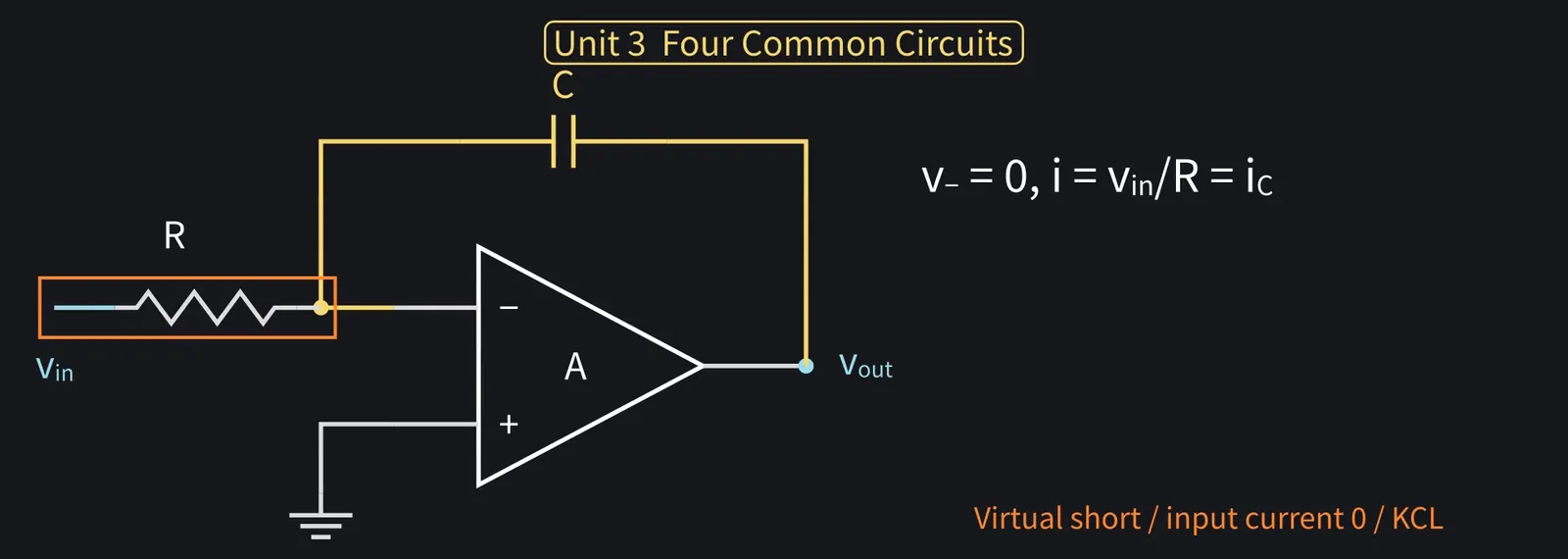
Fourth, the integrator. Keep the inverting amp's input resistor Rin, which we'll now just call R, and replace only Rf with a capacitor C.

Illustration: Fourth, the integrator. Keep the inverting amp's input resistor Rin, which we'll now just call R, and replace only Rf with a capacitor C.
Figure 64

ZundamonQuestion

Can a capacitor really integrate, nanoda?
Shikoku Metan

As before, the − input is 0 V. The current through R is i = vin/R, all flowing into C.

Illustration: As before, the − input is 0 V. The current through R is i = vin/R, all flowing into C.
Figure 65

Shikoku Metan

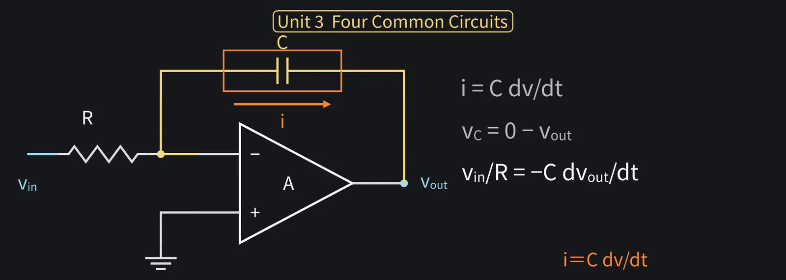
A capacitor's current is proportional to its voltage's rate of change: i = C × dv/dt.

Illustration: A capacitor's current is proportional to its voltage's rate of change: i = C × dv/dt.
Figure 66

Shikoku Metan

Current flows from the − input side to the output. Take C's voltage that way: 0−vout.

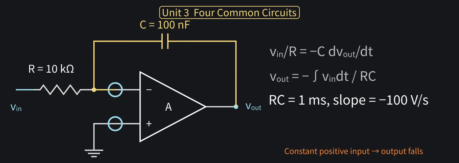
Shikoku Metan: So i = C × d(0−vout)/dt. That is, vin/R = −C × dvout/dt.

Illustration: So i = C × d(0 − vout)/dt. That is, vin/R = −C × dvout/dt.
Figure 67

Shikoku Metan

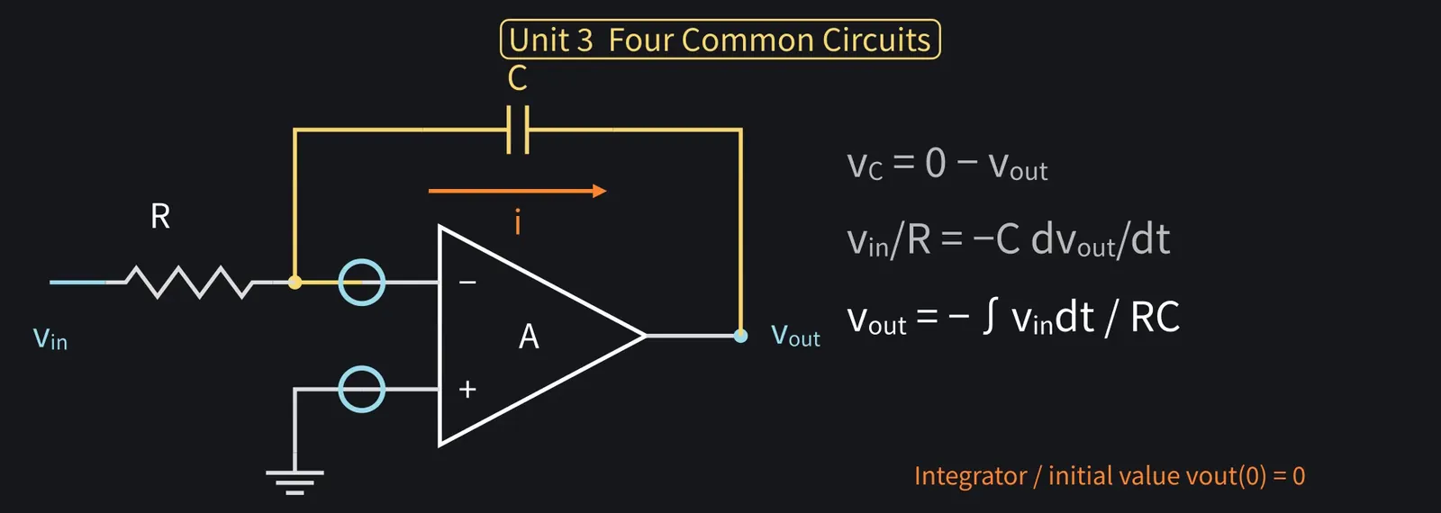
Integrate both sides. Starting the output at 0 V: vout = −(1/RC)∫vin dt.

Illustration: Integrate both sides. Starting the output at 0 V: vout = −(1/RC)∫vin dt.
Figure 68

Zundamon

The current piles up as charge in C. That's why it integrates, nanoda!
Shikoku Metan

With R = 10 kΩ and C = 100 nF, RC = 1 ms. For a +0.1 V input, the output falls 0.1 V every millisecond.

Illustration: With R = 10 kΩ and C = 100 nF, RC = 1 ms. For a +0.1 V input, the output falls 0.1 V every millisecond.
Figure 69

Zundamon

A square wave, + and − of equal size and time, becomes a triangle wave, nanoda!
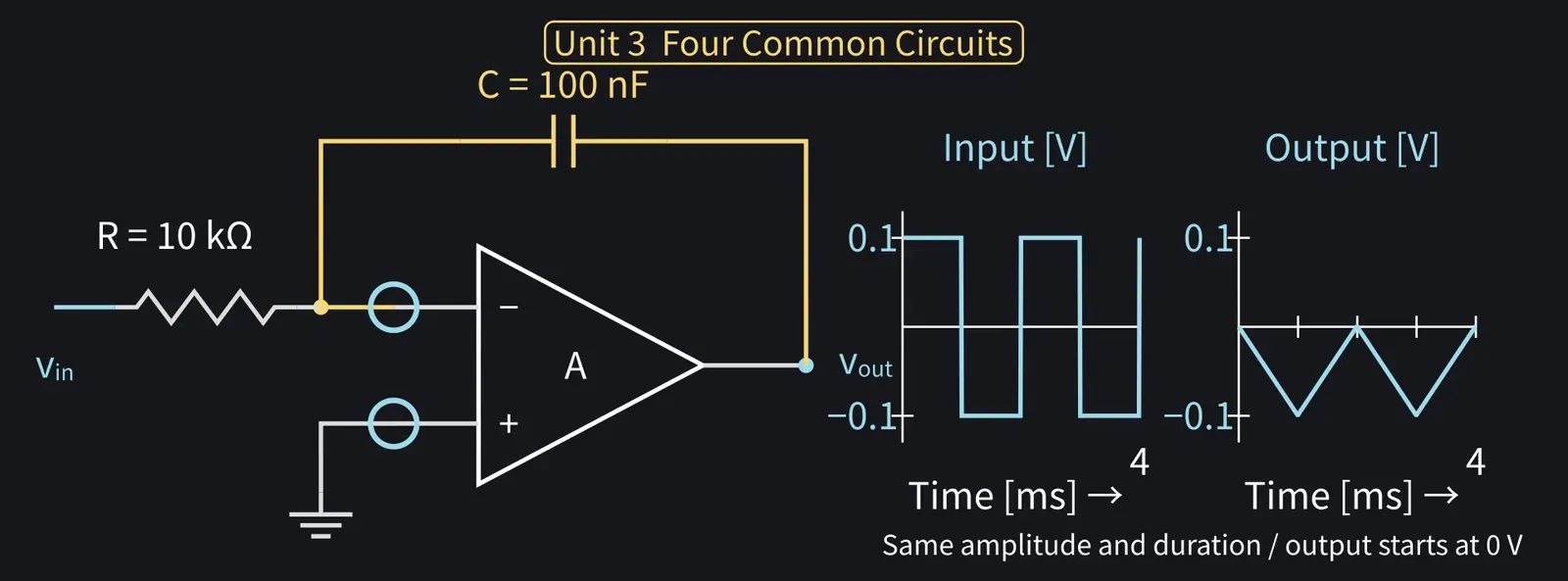
Illustration: A square wave, + and − of equal size and time, becomes a triangle wave, nanoda!
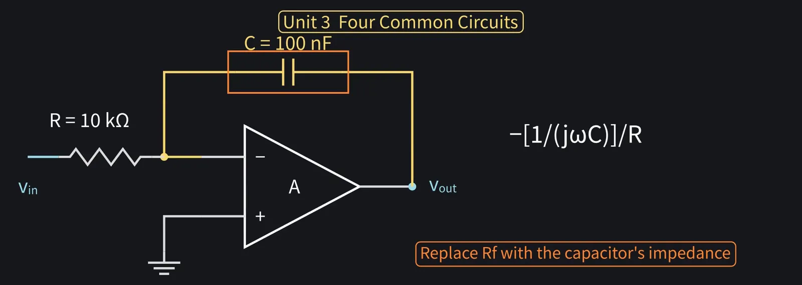
Figure 70

Shikoku Metan

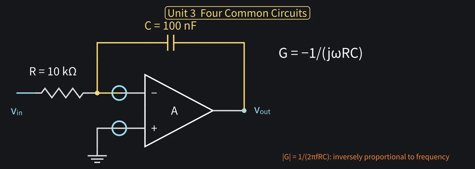
In frequency terms, take the inverting-amp gain and replace Rf with C's impedance, 1/(jωC).

Illustration: In frequency terms, take the inverting-amp gain and replace Rf with C's impedance, 1/(jωC).
Figure 71

Shikoku Metan

Gain is −1/(jωRC). Magnitude falls with frequency: 10× the frequency, 1/10 the output.

Illustration: Gain is −1/(jωRC). Magnitude falls with frequency: 10× the frequency, 1/10 the output.
Figure 72

Shikoku Metan

Used in filters, waveform generators, control circuits, and many other places.

Illustration: Used in filters, waveform generators, control circuits, and many other places.
Figure 73

Shikoku Metan

Unit 3 recap: follower is 1, non-inverting is 1+Rf/Rg, inverting is −Rf/Rin.

Illustration: Unit 3 recap: follower is 1, non-inverting is 1 + Rf/Rg, inverting is −Rf/Rin.
Figure 74

Shikoku Metan

Integrator: −(1/RC)∫vin dt. In each, the external parts set the function.

Illustration: Integrator: −(1/RC)∫vin dt. In each, the external parts set the function.
Figure 75

Zundamon

Fix voltage and current with two rules, then solve with resistor and capacitor equations!
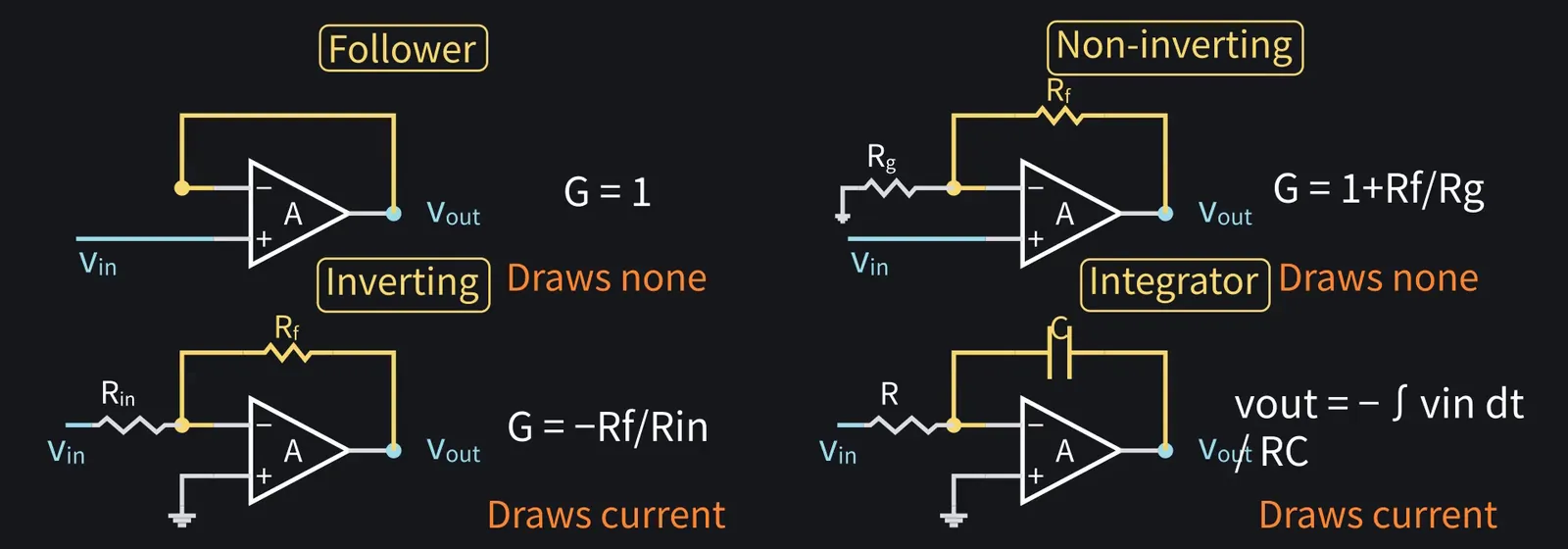
Illustration: Fix voltage and current with two rules, then solve with resistor and capacitor equations!
Figure 76

6Inside CMOS: from a differential pair to two stages

ZundamonQuestion

But what's inside the triangle, nanoda? Is the gain really 100,000?
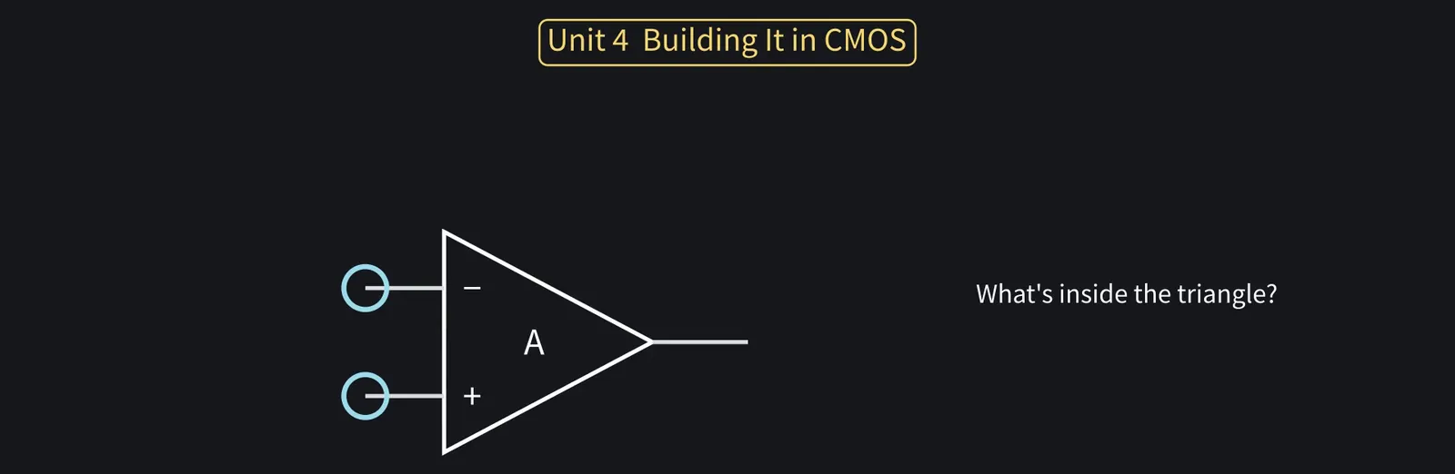
Illustration: But what's inside the triangle, nanoda? Is the gain really 100,000?
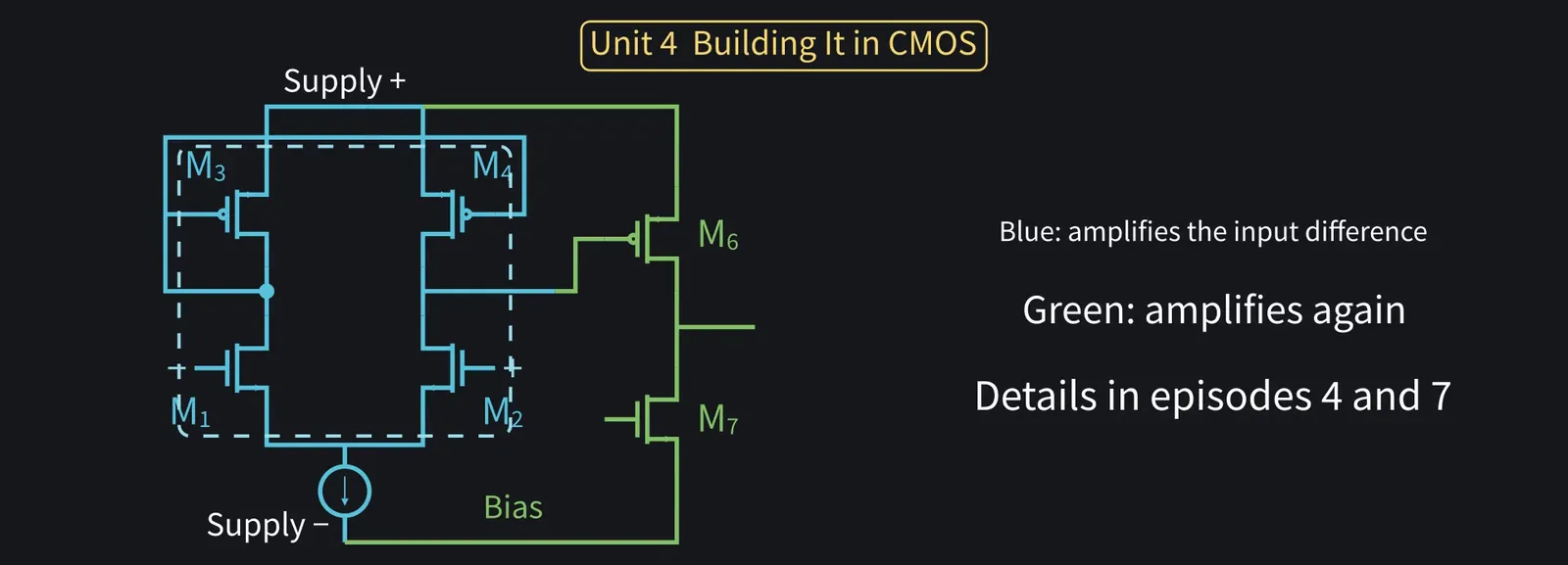
Figure 77

Shikoku Metan

Let's build an IC op-amp step by step, using parts from the earlier episodes.

Illustration: Let's build an IC op-amp step by step, using parts from the earlier episodes.
Figure 78

Shikoku Metan

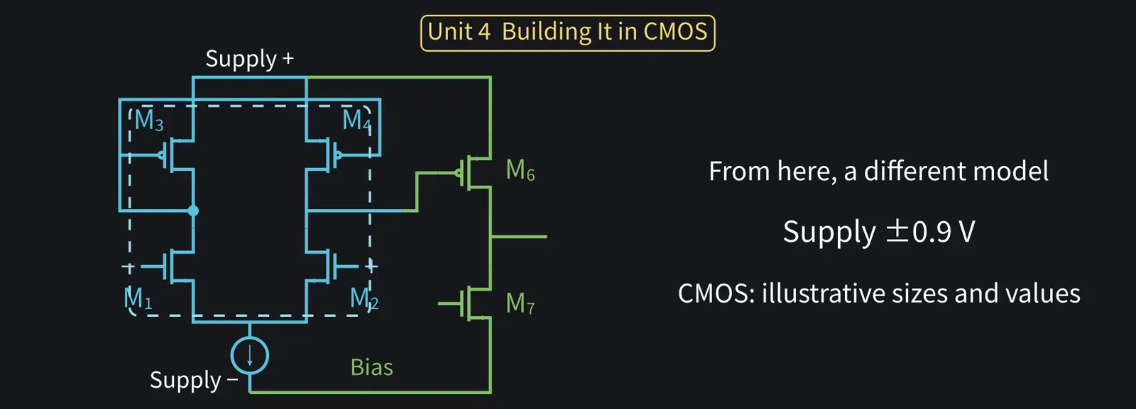
From here we switch models: the supply is the earlier 1.8 V split at its midpoint, so ±0.9 V, with illustrative values for roughly 180 nm CMOS.

Illustration: From here we switch models: the supply is the earlier 1.8 V split at its midpoint, so ±0.9 V, with illustrative values for roughly 180 nm CMOS.
Figure 79

Shikoku Metan

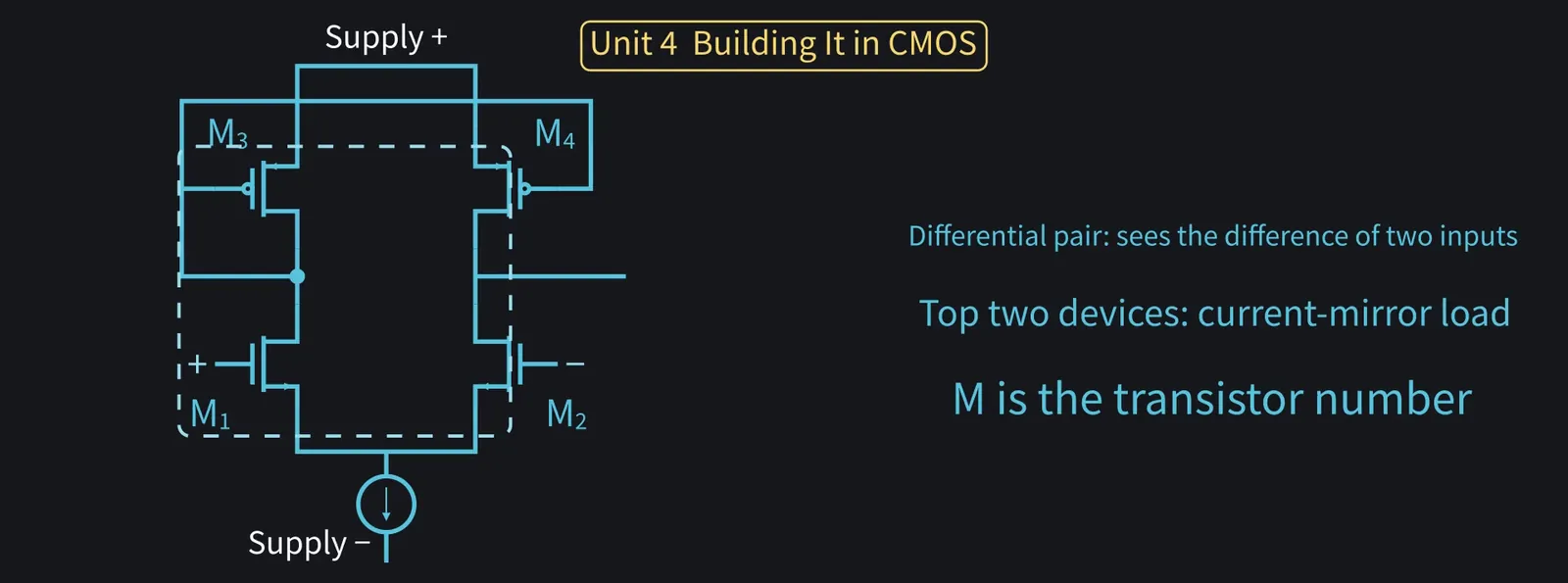
First, recall episode 7's differential pair with a PMOS current mirror load.

Illustration: First, recall episode 7's differential pair with a PMOS current mirror load.
Figure 80

Shikoku Metan

Two inputs, one output, amplifying the difference. That alone is already an op-amp.

Illustration: Two inputs, one output, amplifying the difference. That alone is already an op-amp.
Figure 81

ZundamonQuestion

Wow, episode 7's circuit is the inside of the triangle, nanoda?
Shikoku Metan

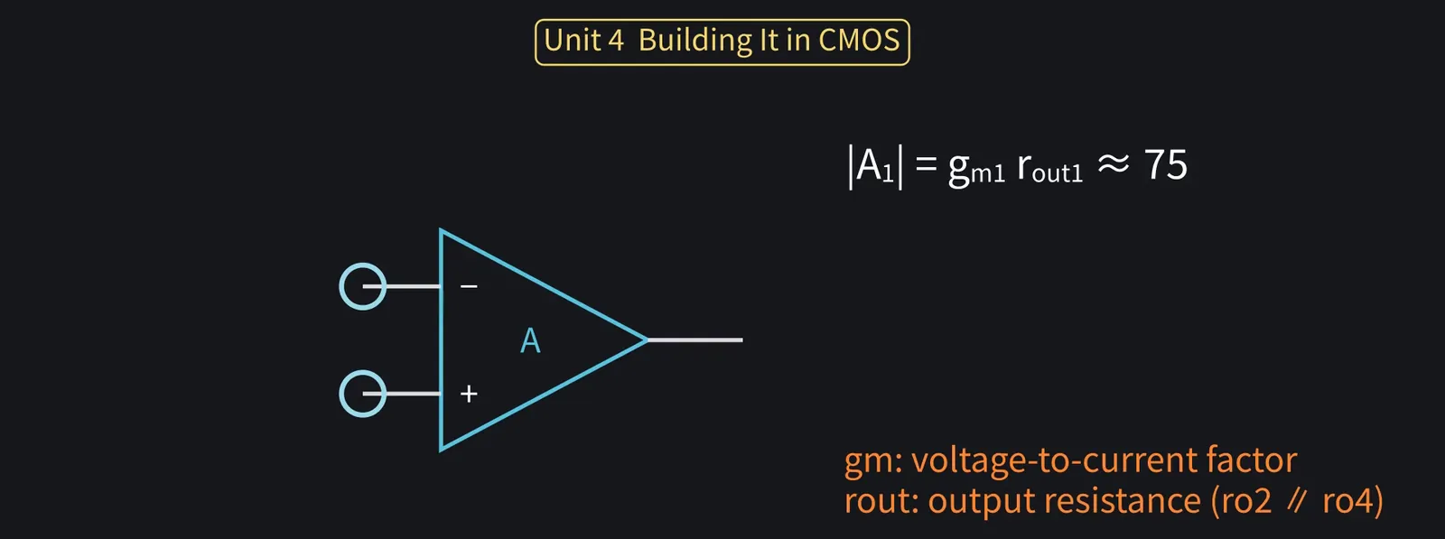
Yes. The gain magnitude is gm(ro∥ro), as in episode 7. With this example's transistor sizes it's about 75.

Illustration: Yes. The gain magnitude is gm(ro∥ro), as in episode 7. With this example's transistor sizes it's about 75.
Figure 82

Shikoku Metan

Let's make a non-inverting gain of 10. Treat vin and vout as small changes from the bias.

Illustration: Let's make a non-inverting gain of 10. Treat vin and vout as small changes from the bias.
Figure 83

Shikoku Metan

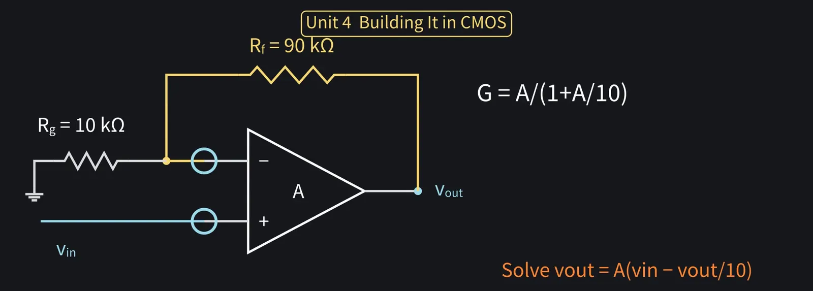
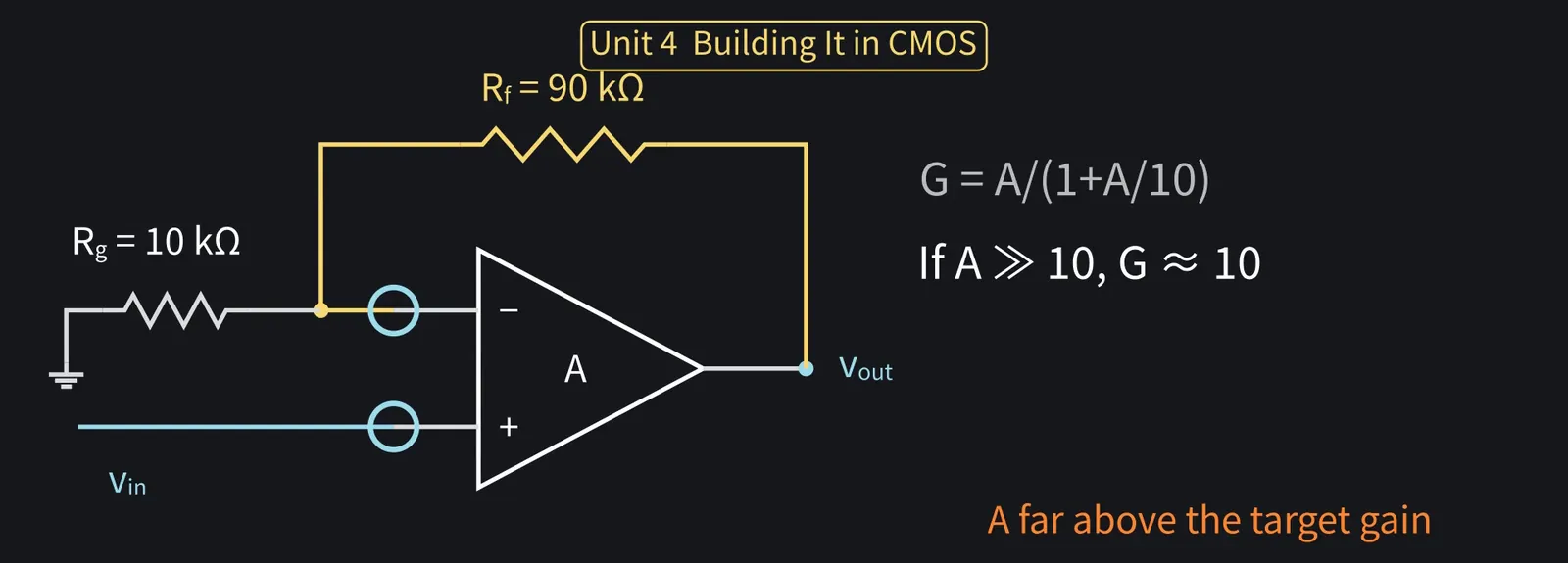
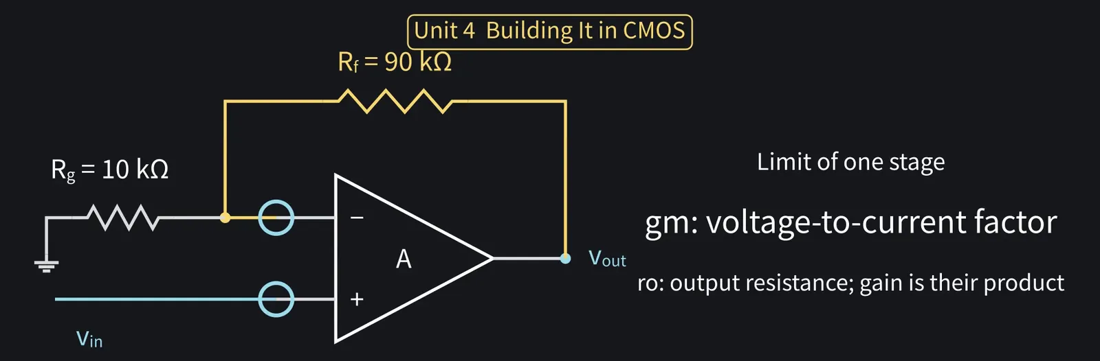
With finite A, the voltage fed back to the − input is vout×Rg/(Rf+Rg) = vout/10, so vout = A(vin−vout/10). Solving gives a gain of A/(1 + A/10).

Illustration: With finite A, the voltage fed back to the − input is vout × Rg/(Rf + Rg) = vout/10, so vout = A(vin − vout/10). Solving gives a gain of A/(1 + A/10).
Figure 84

Shikoku Metan

If A is far above 10, it's nearly 10. That's the assumption behind the voltage rule.

Illustration: If A is far above 10, it's nearly 10. That's the assumption behind the voltage rule.
Figure 85

Shikoku Metan

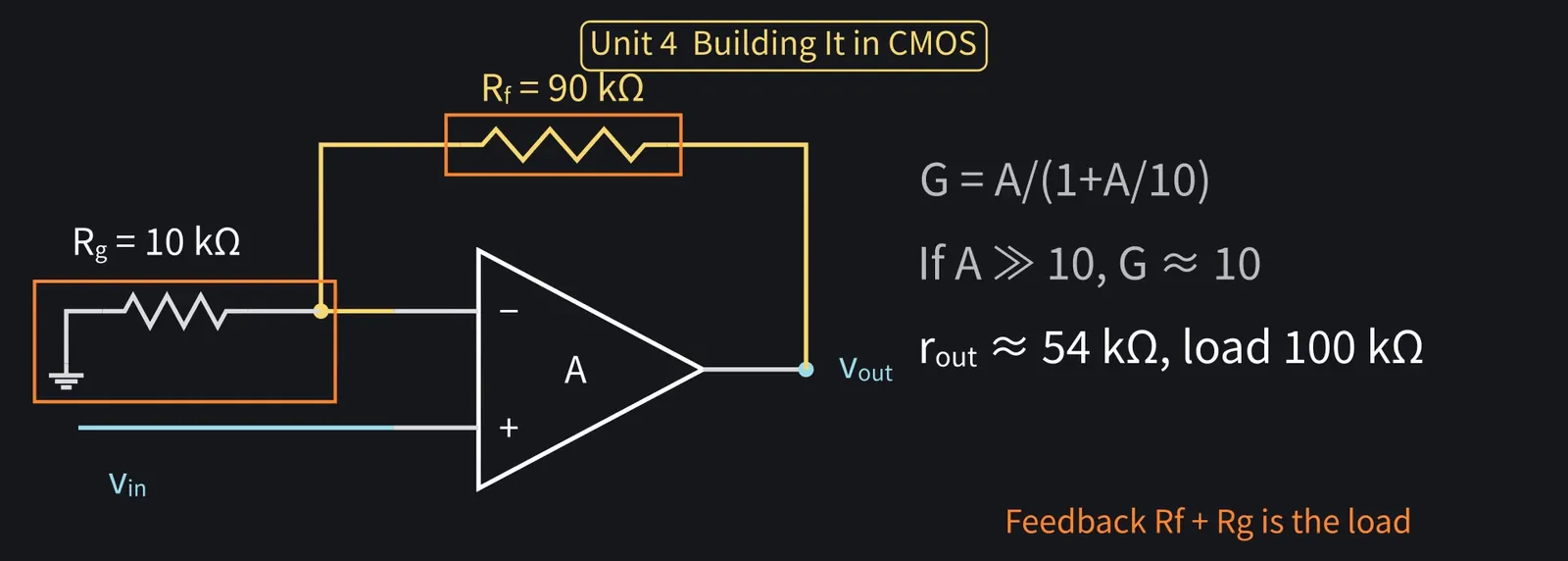
And unlike the ideal 0, this stage's output resistance is about 54 kΩ. The feedback resistors Rf+Rg=100 kΩ hang on the output as a load.

Illustration: And unlike the ideal 0, this stage's output resistance is about 54 kΩ. The feedback resistors Rf + Rg = 100 kΩ hang on the output as a load.
Figure 86

Shikoku Metan

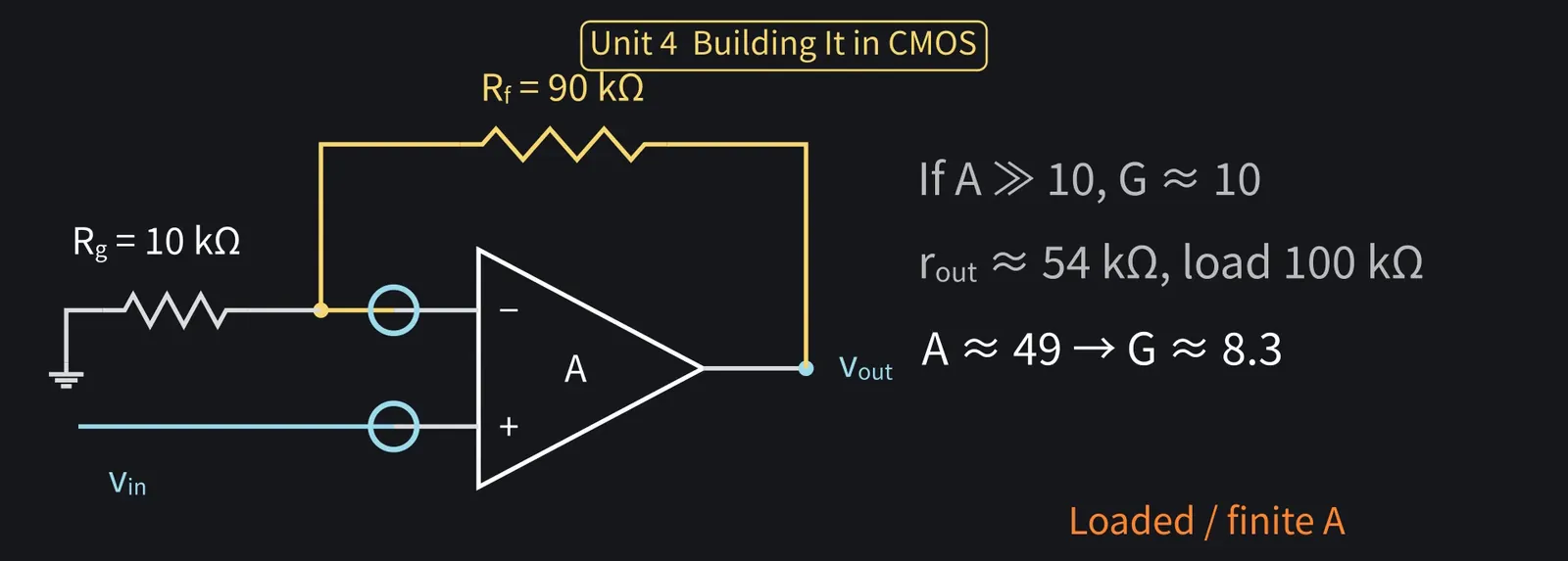
Gain with the load is about 49. So the intended 10 becomes only about 8.3.

Illustration: Gain with the load is about 49. So the intended 10 becomes only about 8.3.
Figure 87

Zundamon

8.3 times, nanoda?! That's nowhere near the assignment's 10!
Shikoku Metan

One stage's gain is set by gm times ro, so there's a limit to how large it gets.

Illustration: One stage's gain is set by gm times ro, so there's a limit to how large it gets.
Figure 88

Shikoku Metan

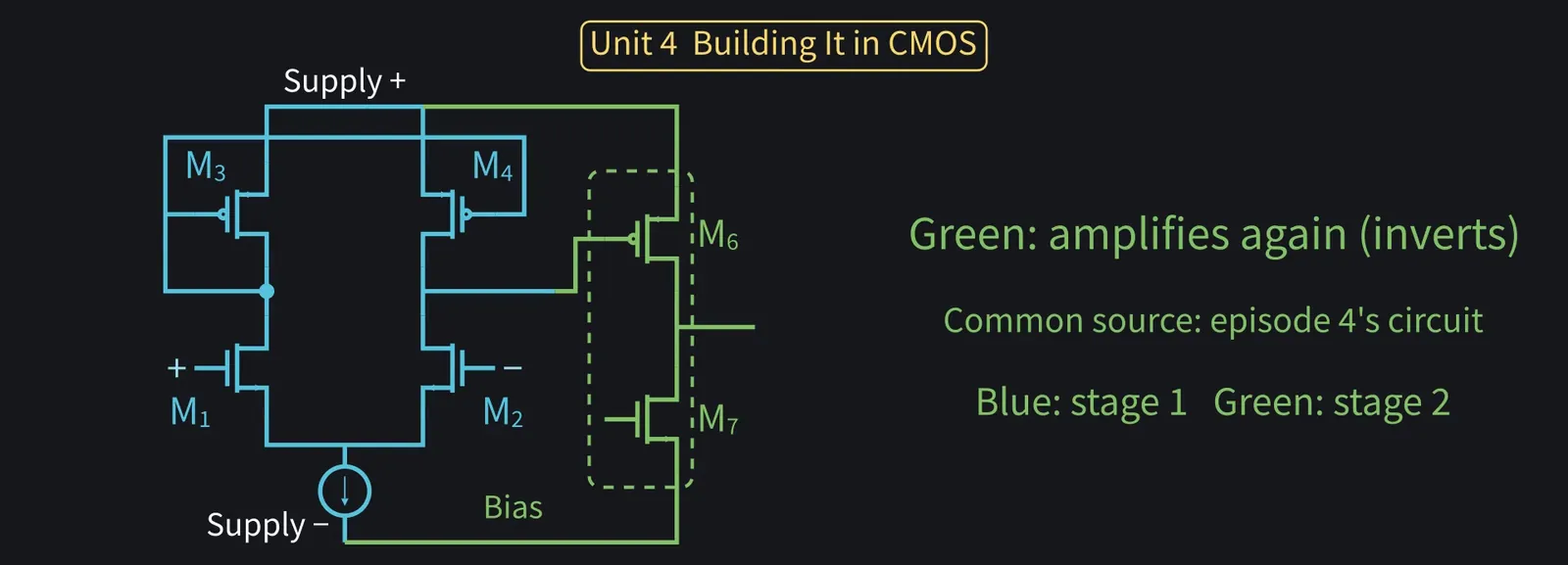
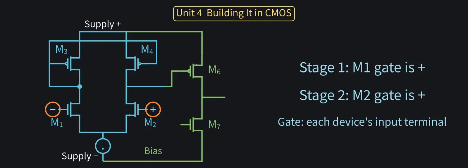
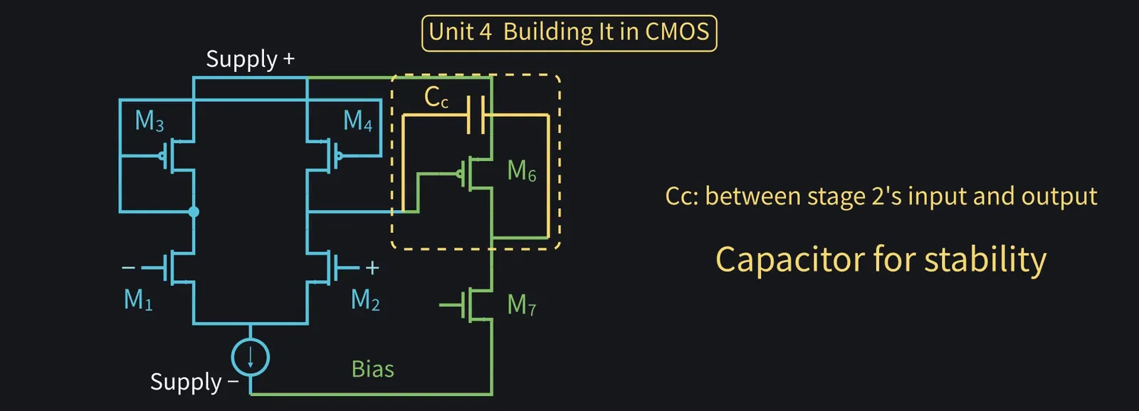
So add another stage: episode 4's common-source amp with a current source load.

Illustration: So add another stage: episode 4's common-source amp with a current source load.
Figure 89

Shikoku Metan

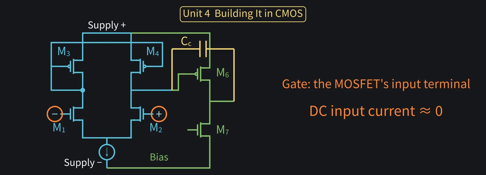
The second stage inverts, so the + and − labels swap compared with the single stage. With one stage, M1's gate was the + input; with two stages, M2's gate is the + input.

Illustration: The second stage inverts, so the + and − labels swap compared with the single stage. With one stage, M1's gate was the + input; with two stages, M2's gate is the + input.
Figure 90

Shikoku Metan

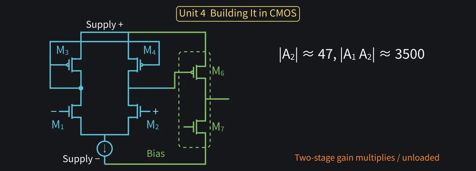
The second stage's gain magnitude is about 47. Multiplied, the total is about 3500.

Illustration: The second stage's gain magnitude is about 47. Multiplied, the total is about 3500.
Figure 91

Shikoku Metan

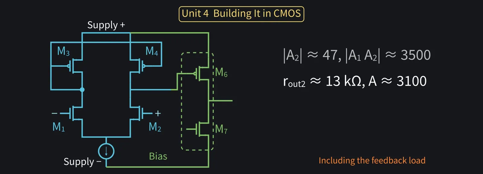
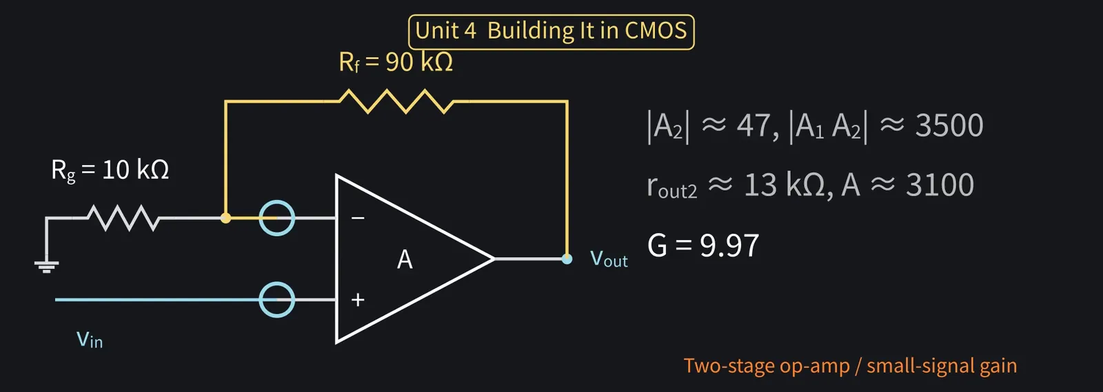
The second stage's output resistance is smaller, about 13 kΩ, so even with the feedback resistors as a load the total gain stays near 3100.

Illustration: The second stage's output resistance is smaller, about 13 kΩ, so even with the feedback resistors as a load the total gain stays near 3100.
Figure 92

Shikoku Metan

Then the gain-of-10 non-inverting amplifier gives about 9.97. Nearly on target.

Illustration: Then the gain-of-10 non-inverting amplifier gives about 9.97. Nearly on target.
Figure 93

Zundamon

From 8.3 to 9.97! Adding a stage brought it right up toward 10, nanoda!
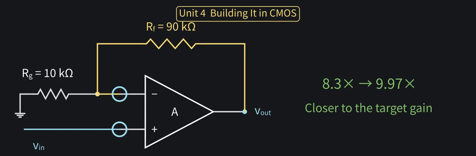
Illustration: From 8.3 to 9.97! Adding a stage brought it right up toward 10, nanoda!
Figure 94

Zundamon

Still, it doesn't reach a general-purpose part's 100,000.
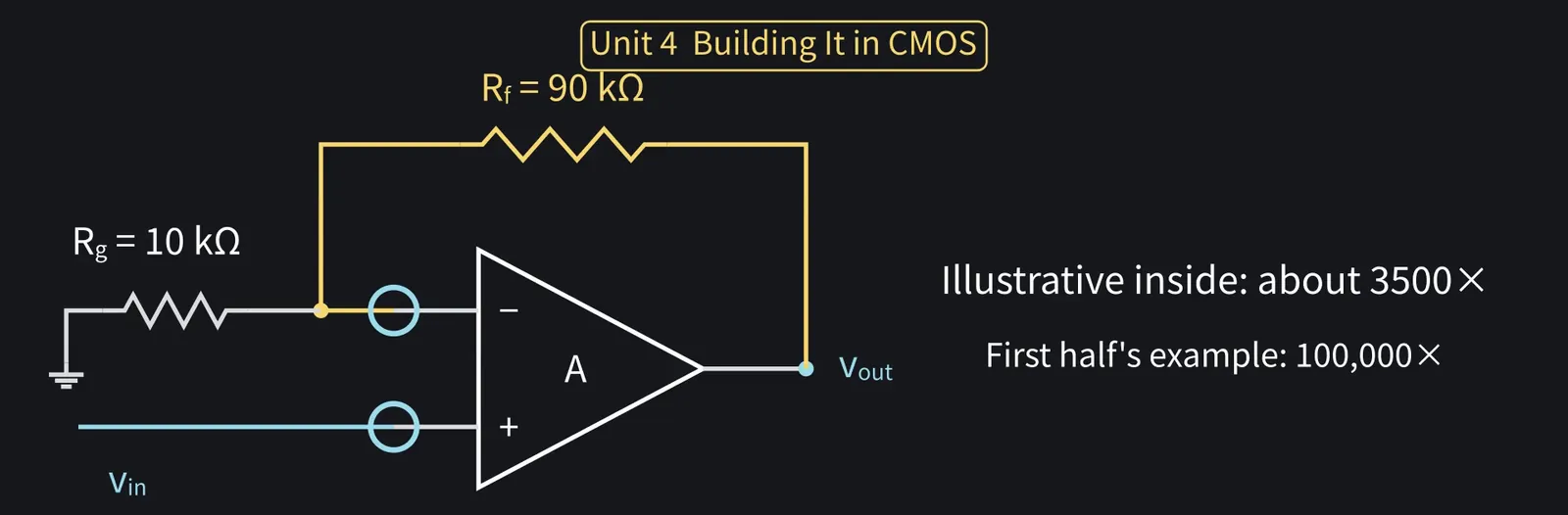
Illustration: Still, it doesn't reach a general-purpose part's 100,000.
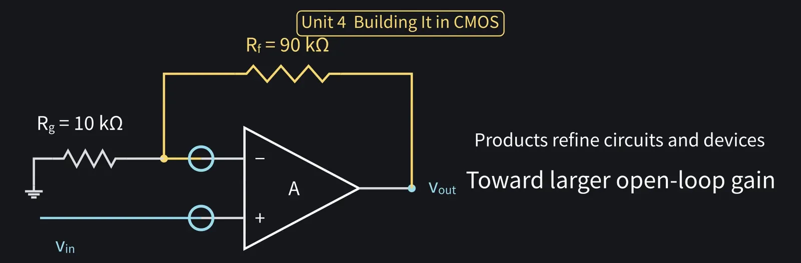
Figure 95

Shikoku Metan

Not in this simple form. Products tune the transistors and circuit to go much higher.

Illustration: Not in this simple form. Products tune the transistors and circuit to go much higher.
Figure 96

Shikoku Metan

A capacitor Cc, here 2 pF, goes between stage 2's input and output. It keeps the amplifier stable; the details come in a later episode.

Illustration: A capacitor Cc, here 2 pF, goes between stage 2's input and output. It keeps the amplifier stable; the details come in a later episode.
Figure 97

Shikoku Metan

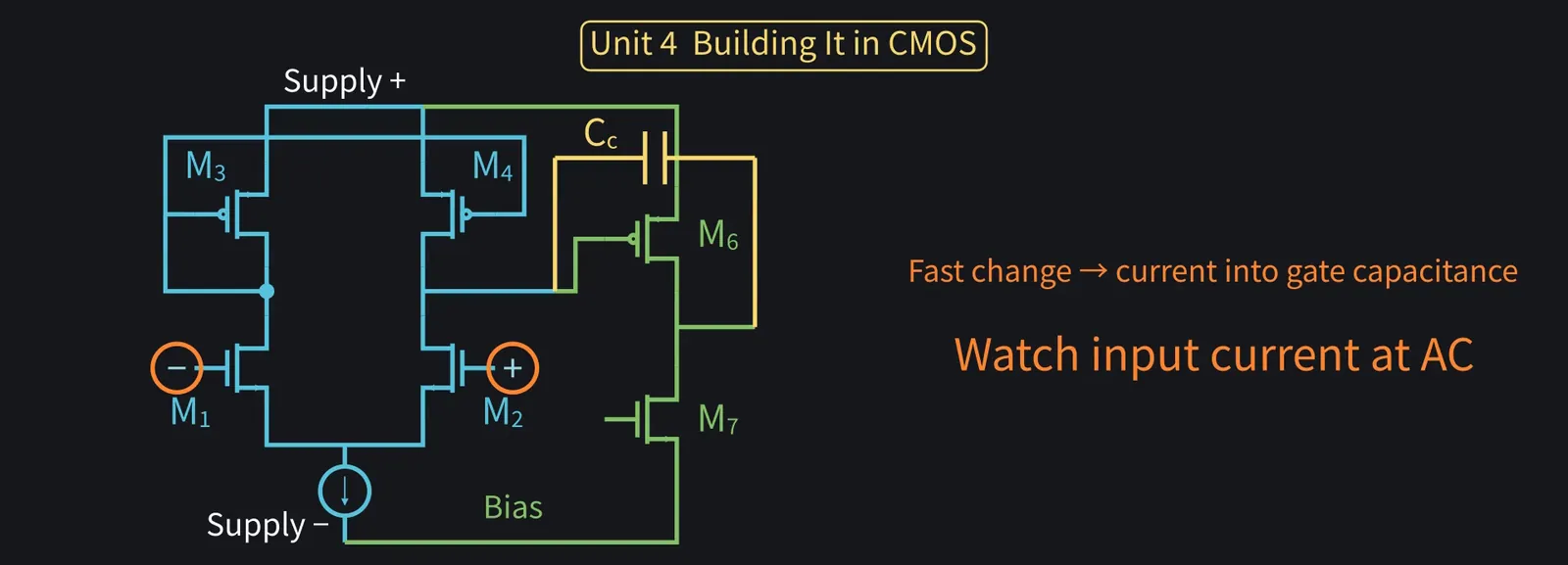
The input is a MOSFET gate. Almost no DC current flows, so the current rule holds well.

Illustration: The input is a MOSFET gate. Almost no DC current flows, so the current rule holds well.
Figure 98

Shikoku Metan

But for fast-changing signals, a little current flows into the gate capacitance.

Illustration: But for fast-changing signals, a little current flows into the gate capacitance.
Figure 99

Shikoku Metan

Unit 4 recap: one differential stage is an op-amp but lacks gain. Two stages multiply it.

Illustration: Unit 4 recap: one differential stage is an op-amp but lacks gain. Two stages multiply it.
Figure 100

7Bandwidth, output swing, and offset limits

Shikoku Metan

Besides gain, there are other internal limits. Let's see how they affect the circuits.

Illustration: Besides gain, there are other internal limits. Let's see how they affect the circuits.
Figure 101

Shikoku Metan

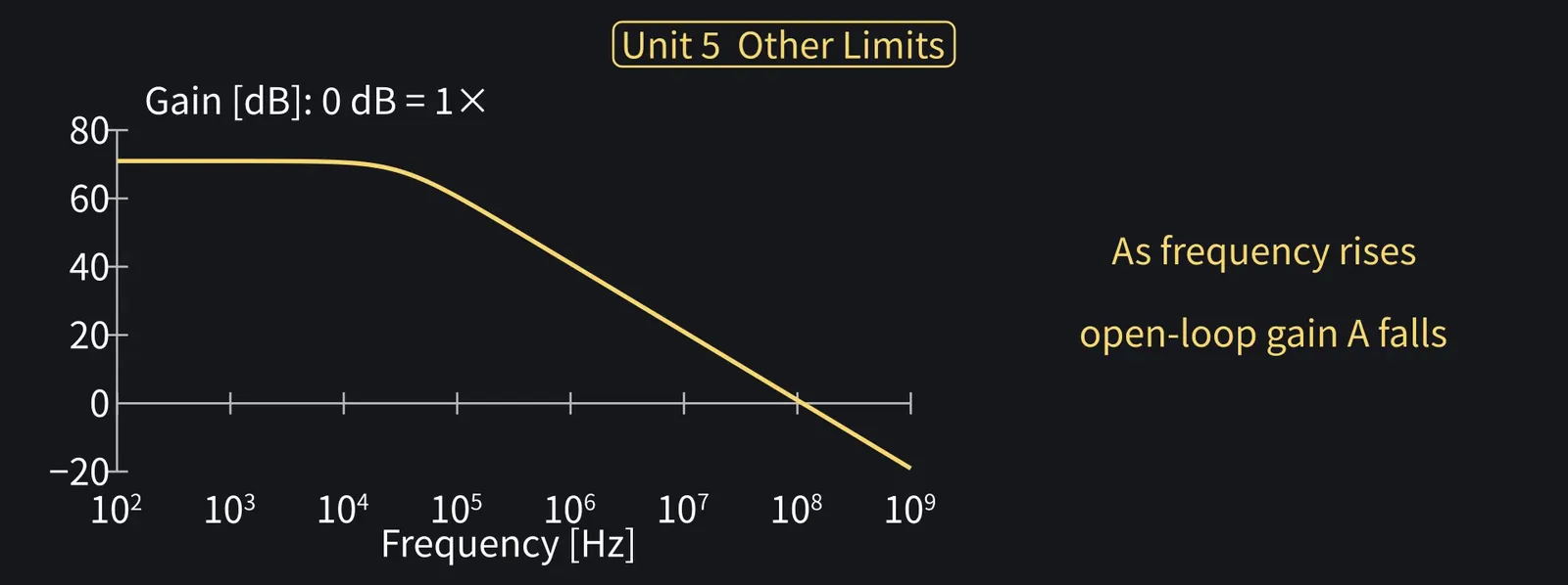
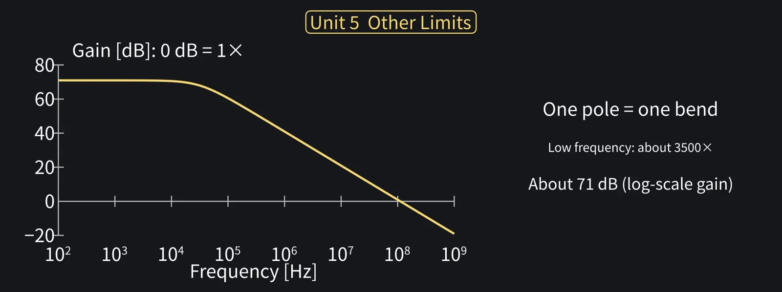
Next, frequency. The internal gain A falls as frequency rises.

Illustration: Next, frequency. The internal gain A falls as frequency rises.
Figure 102

ZundamonQuestion

Huh? Isn't it always 3500, nanoda?
Shikoku Metan

Here, we model A's frequency response with a single pole.

Illustration: Here, we model A's frequency response with a single pole.
Figure 103

Shikoku Metan

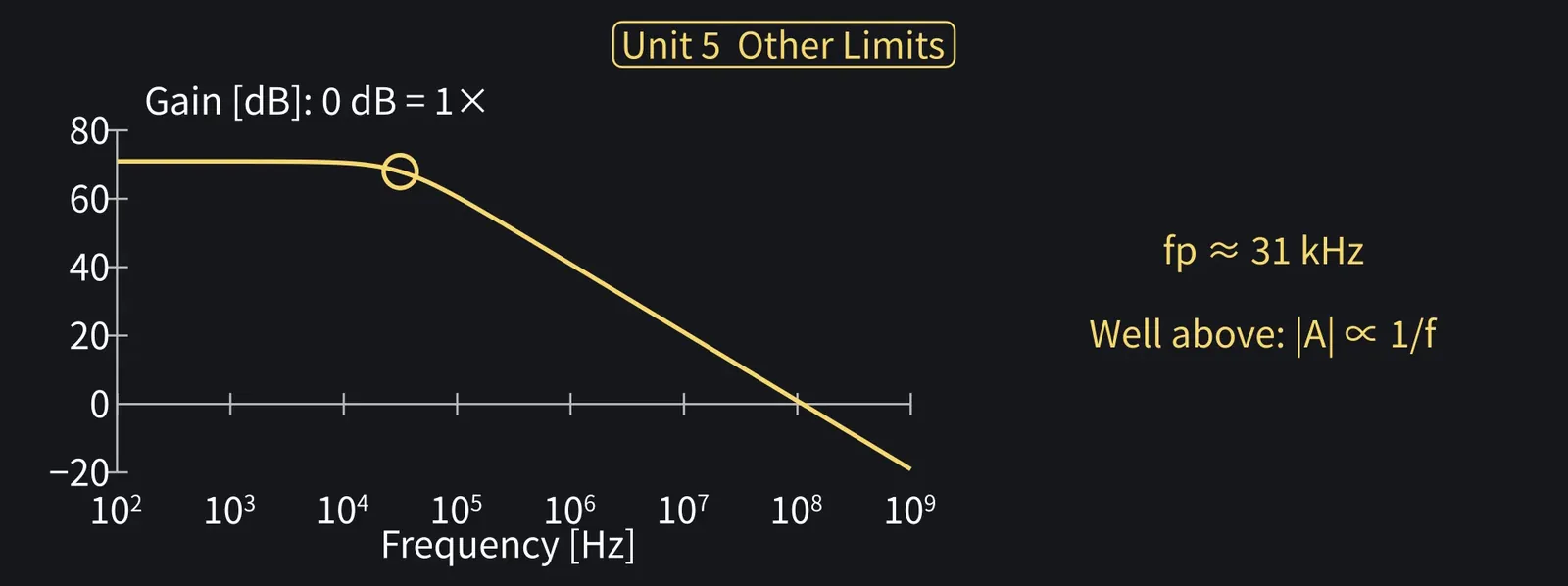
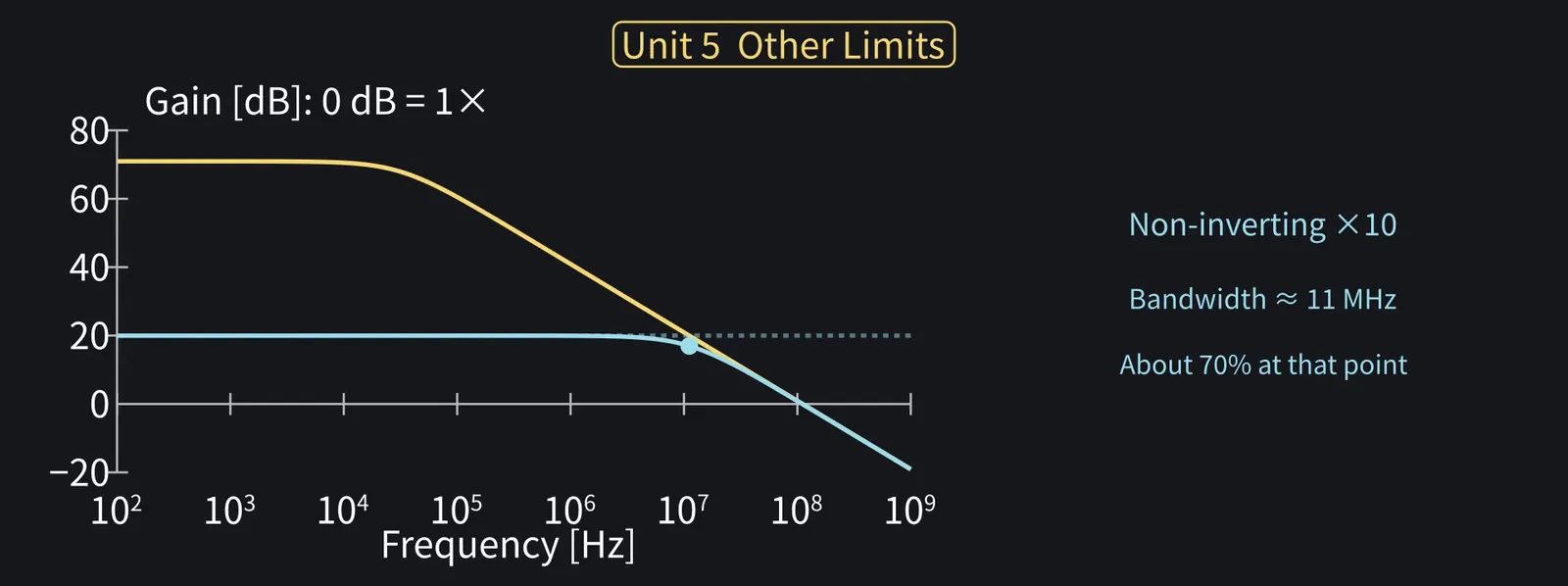
Because of Cc, A falls from about 31 kHz; well above that, it's proportional to 1/f.

Illustration: Because of Cc, A falls from about 31 kHz; well above that, it's proportional to 1/f.
Figure 104

Shikoku Metan

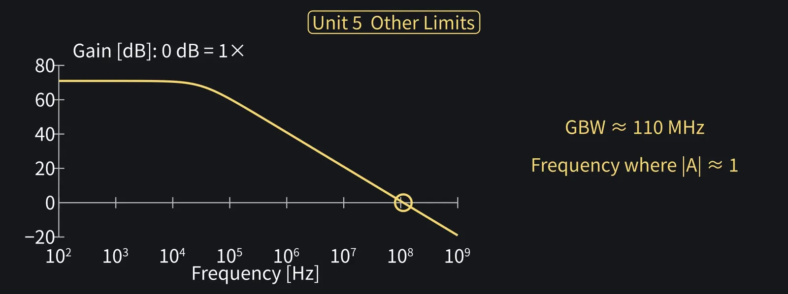
The frequency where A falls to 1 is about 110 MHz. In this approximation it equals the low-frequency gain times the pole frequency, 3500×31 kHz: the gain-bandwidth product, GBW.

Illustration: The frequency where A falls to 1 is about 110 MHz. In this approximation it equals the low-frequency gain times the pole frequency, 3500 × 31 kHz: the gain-bandwidth product, GBW.
Figure 105

Shikoku Metan

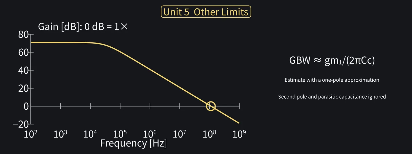
In this approximation, GBW is set by the first stage's gm and by Cc: GBW ≈ gm/(2πCc). With gm≈1.4 mS and Cc=2 pF, that's about 110 MHz.

Illustration: In this approximation, GBW is set by the first stage's gm and by Cc: GBW ≈ gm/(2πCc). With gm ≈ 1.4 mS and Cc = 2 pF, that's about 110 MHz.
Figure 106

Shikoku Metan

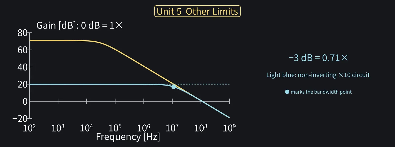
Bandwidth is where gain drops 3 dB, to about 70% of its low-frequency value.

Illustration: Bandwidth is where gain drops 3 dB, to about 70% of its low-frequency value.
Figure 107

Shikoku Metan

For the gain-of-10 non-inverting amp, bandwidth is about GBW/10: about 11 MHz.

Illustration: For the gain-of-10 non-inverting amp, bandwidth is about GBW/10: about 11 MHz.
Figure 108

Zundamon

At a gain of 100, bandwidth is about 1.1 MHz. Gain and bandwidth trade off, nanoda!
Shikoku Metan

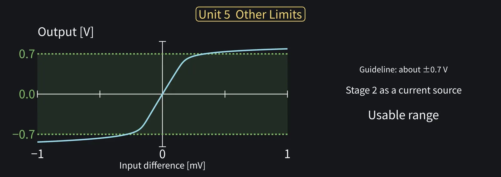
The output range has a guideline: stage 2 acts as a current source to about ±0.7 V.

Illustration: The output range has a guideline: stage 2 acts as a current source to about ±0.7 V.
Figure 109

Shikoku Metan

Beyond that the output still moves a little, but the gain drops sharply.

Zundamon

0.1 V times 10 is 1 V. With this inside, it can't cleanly do 10 times, nanoda!
Shikoku Metan

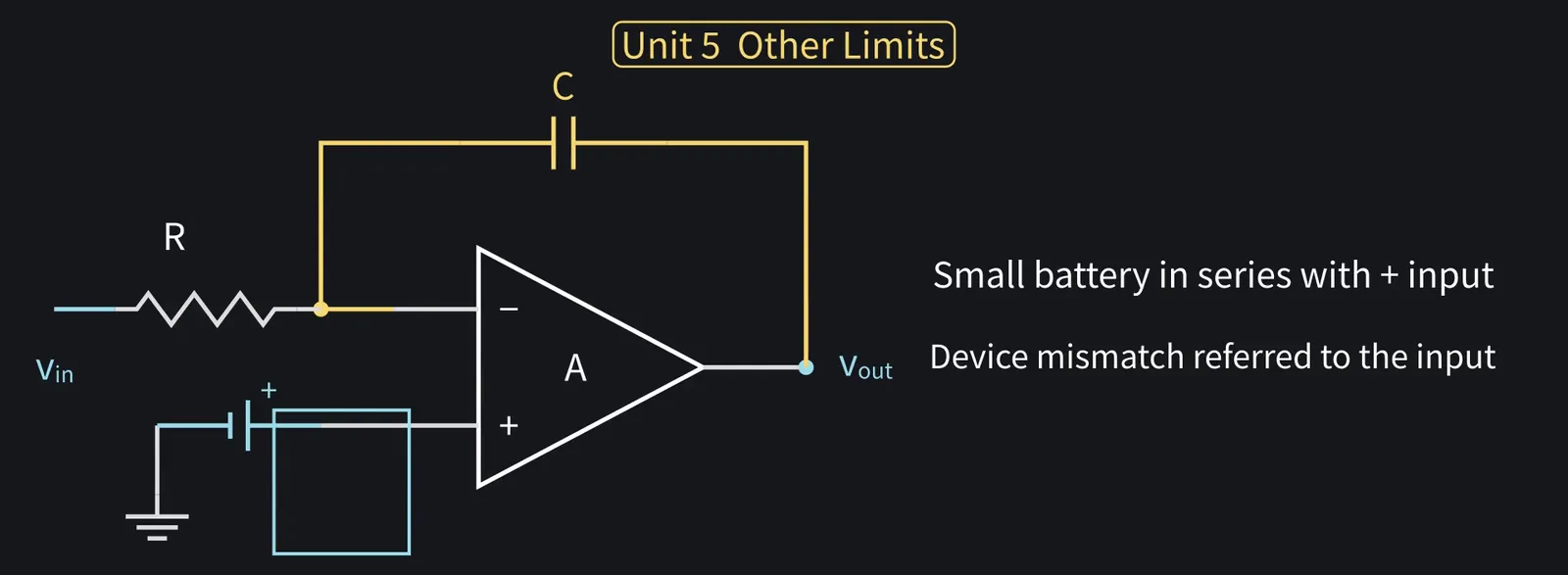
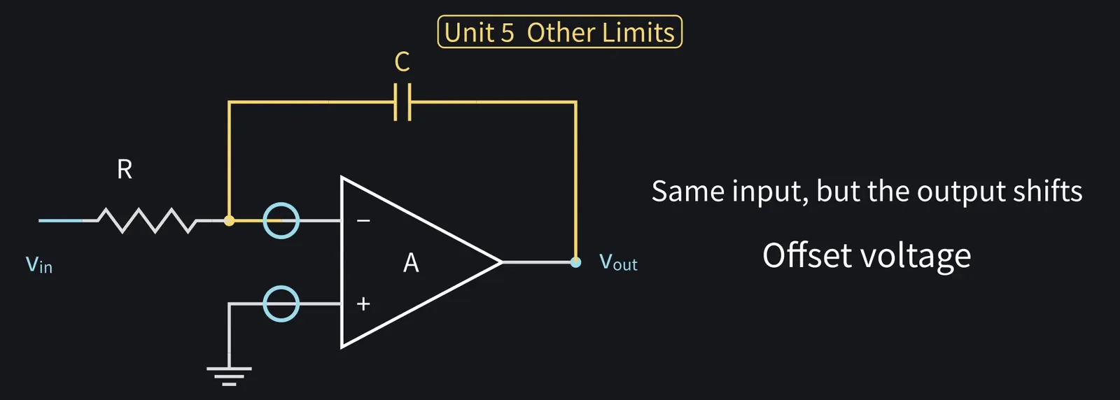
Last, offset voltage. Even with both inputs at the same voltage, the output is shifted.

Illustration: Last, offset voltage. Even with both inputs at the same voltage, the output is shifted.
Figure 110

Shikoku Metan

Tiny differences between devices act like a small battery at the input.

Illustration: Tiny differences between devices act like a small battery at the input.
Figure 111

Shikoku Metan

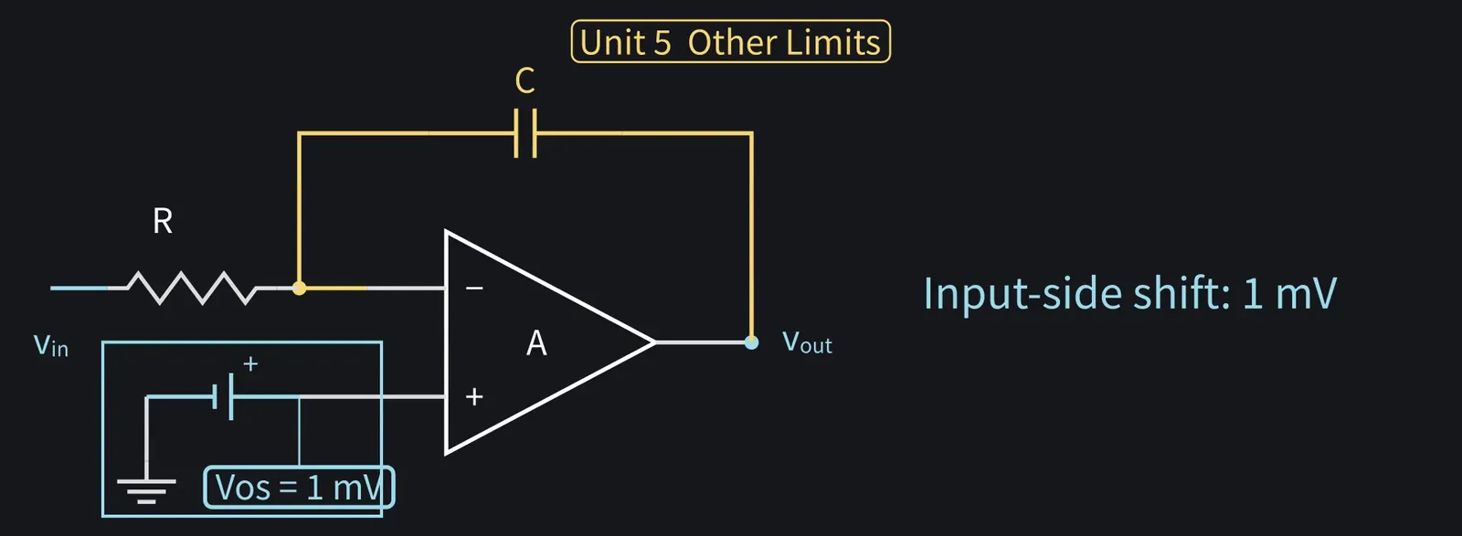
Here we'll model it as a 1 mV offset in series with the + input.

Illustration: Here we'll model it as a 1 mV offset in series with the + input.
Figure 112

Shikoku Metan

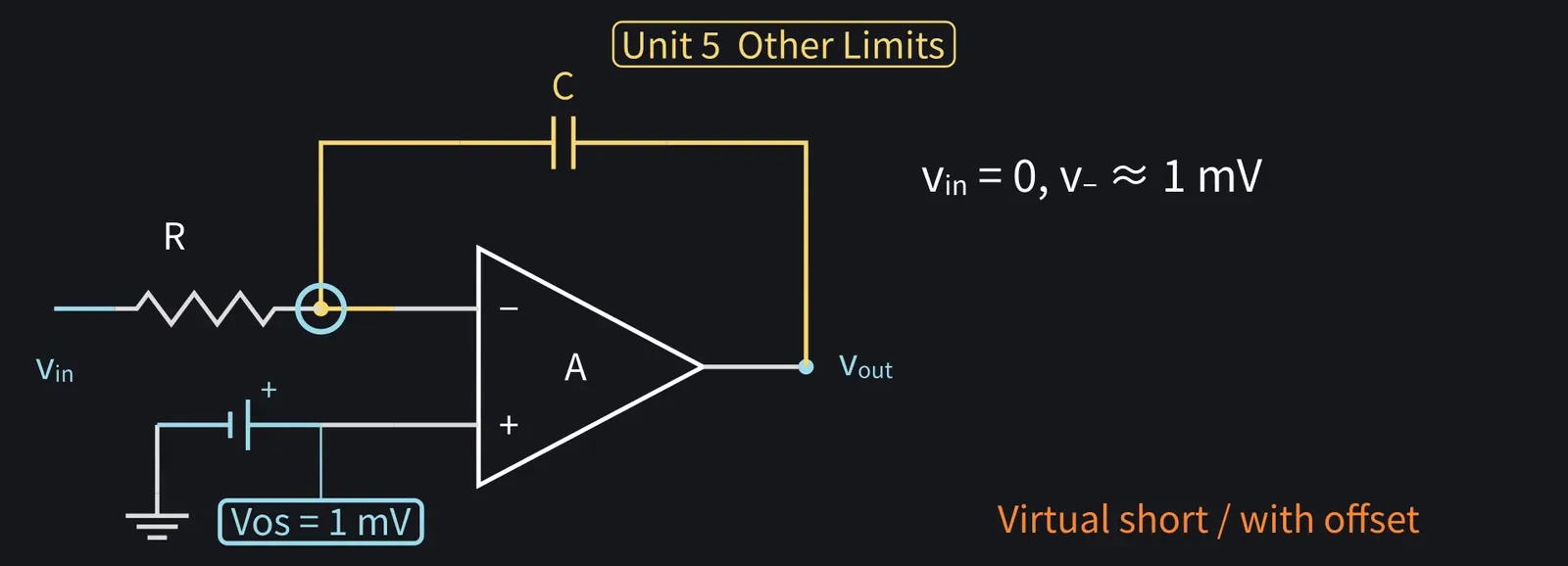
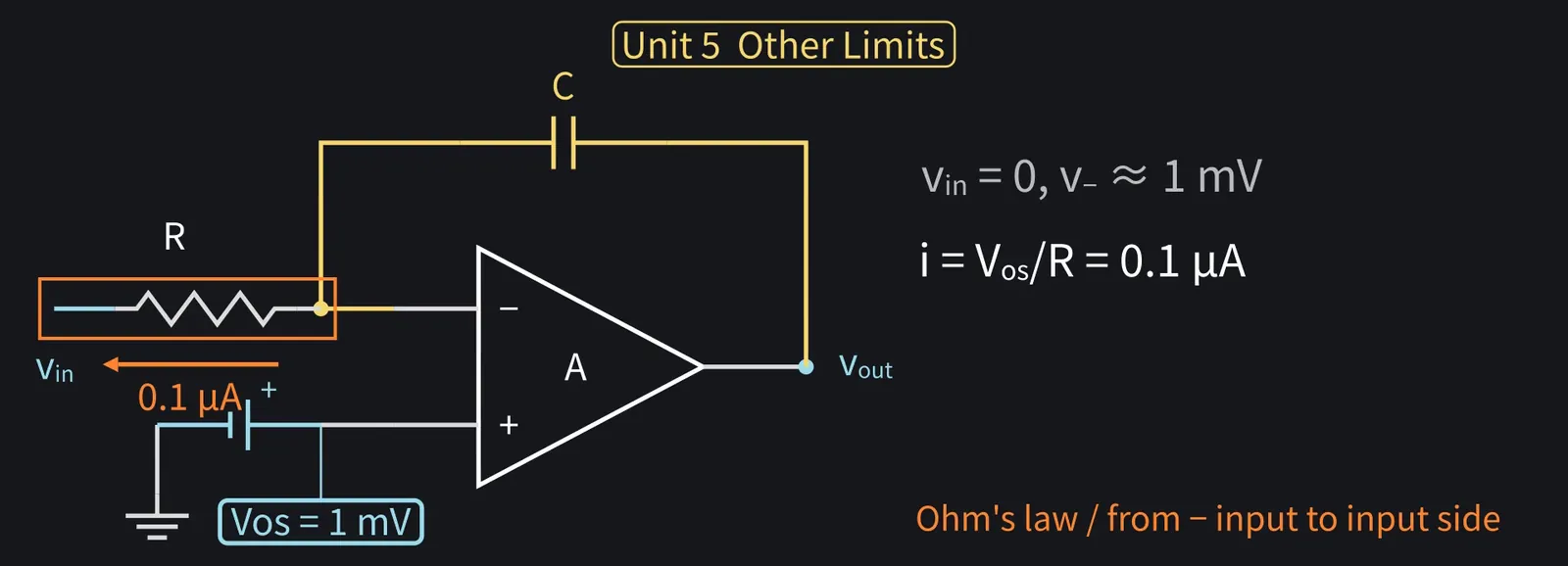
Even with the integrator's input at 0 V, the − input is held near 1 mV, not 0 V.

Illustration: Even with the integrator's input at 0 V, the − input is held near 1 mV, not 0 V.
Figure 113

Shikoku Metan

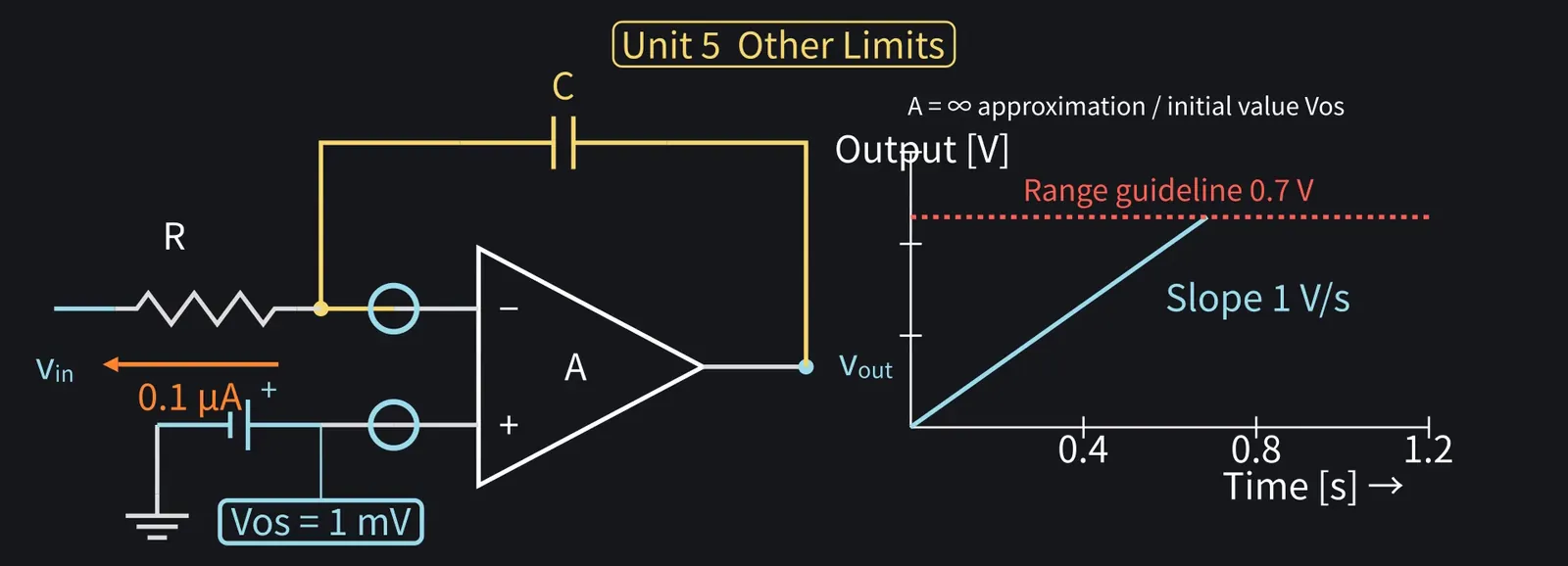
So 1 mV÷10 kΩ=0.1 µA keeps flowing through R. It all passes through C, so the output keeps rising.

Illustration: So 1 mV ÷ 10 kΩ = 0.1 µA keeps flowing through R. It all passes through C, so the output keeps rising.
Figure 114

Shikoku Metan

With RC = 1 ms, the output rises about 1 V per second, so it passes the output-range guideline within a second.

Illustration: With RC = 1 ms, the output rises about 1 V per second, so it passes the output-range guideline within a second.
Figure 115

Zundamon

The input is 0, yet the output runs off to the edge and sticks, nanoda!
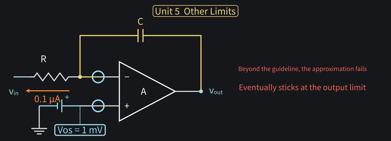
Illustration: The input is 0, yet the output runs off to the edge and sticks, nanoda!
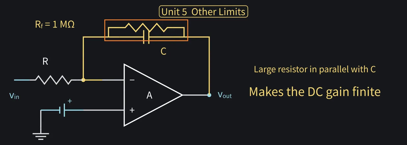
Figure 116

Shikoku Metan

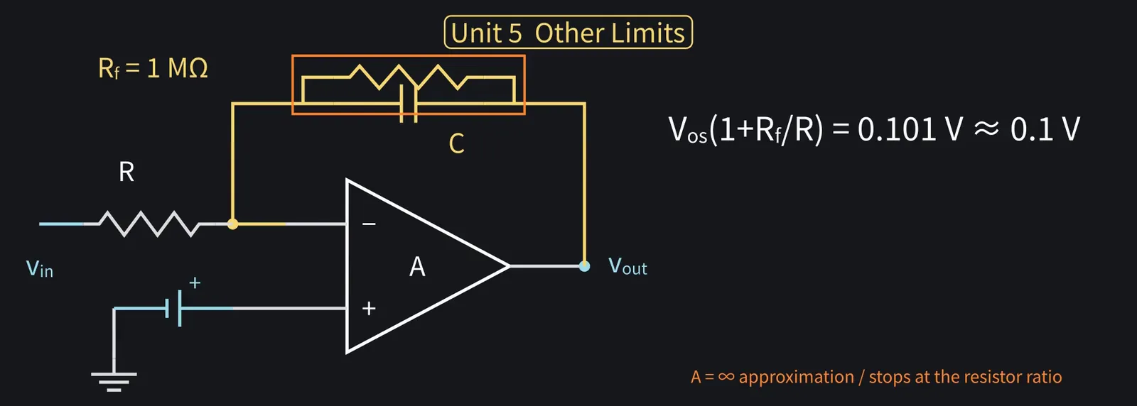
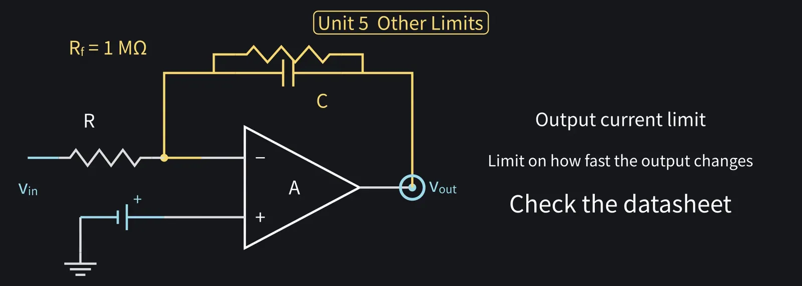
The fix is a large resistor in parallel with C. That makes the DC gain finite.

Illustration: The fix is a large resistor in parallel with C. That makes the DC gain finite.
Figure 117

Shikoku Metan

With a resistor 100 times R, 1 MΩ, the DC gain is (1+Rf/R) = 101, so the 1 mV offset settles the output at about 0.1 V instead of drifting.

Illustration: With a resistor 100 times R, 1 MΩ, the DC gain is (1 + Rf/R) = 101, so the 1 mV offset settles the output at about 0.1 V instead of drifting.
Figure 118

Shikoku Metan

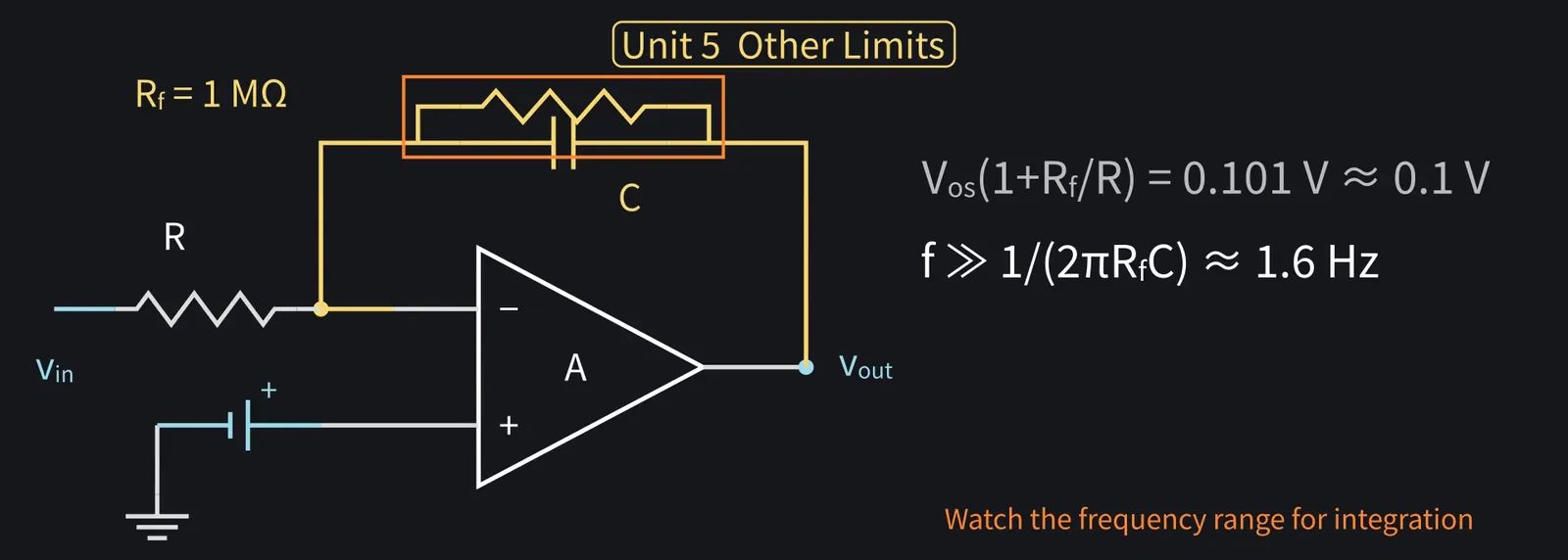
The cost: it only behaves as an integrator well above 1/(2πRfC), about 1.6 Hz.

Illustration: The cost: it only behaves as an integrator well above 1/(2πRfC), about 1.6 Hz.
Figure 119

Shikoku Metan

There are also limits on output current and on how fast the output can change, the slew rate. Check the datasheet.

Illustration: There are also limits on output current and on how fast the output can change, the slew rate. Check the datasheet.
Figure 120

Shikoku Metan

Unit 5 recap: internal gain, bandwidth, output range and offset set accuracy and range.

Illustration: Unit 5 recap: internal gain, bandwidth, output range and offset set accuracy and range.
Figure 121

8Summary: using an op-amp and understanding its internals

Shikoku Metan

Today's recap: an op-amp hugely amplifies the input difference, used with feedback.

Illustration: Today's recap: an op-amp hugely amplifies the input difference, used with feedback.
Figure 122

Zundamon

Infinite gain and input impedance give equal input voltages and zero input current. Real parts only approximate that, nanoda!

Illustration: Infinite gain and input impedance give equal input voltages and zero input current. Real parts only approximate that, nanoda!
Figure 123

Zundamon

10× from a resistor ratio, then check bandwidth and range. Now I can write the report!

Illustration: 10× from a resistor ratio, then check bandwidth and range. Now I can write the report!

Figure 124

Shikoku Metan

Next time: noise basics. When amplifying small signals, what do they get buried in?

Illustration: Next time: noise basics. When amplifying small signals, what do they get buried in?
Figure 125

Zundamon

Thanks for reading, nanoda!