Learn Analog Circuits with Zundamon

Episode 7

Differential Pairs and Active Loads

Amplifying a microphone signal also amplifies its noise. Explore how a differential pair amplifies the difference between two inputs and rejects common-mode interference.

Watch on YouTube (7:01)
  • Shikoku Metan (explains)
  • Zundamon (asks)

1Intro: microphone noise that will not go away

Zundamon

Experiment in trouble! I amplified the mic and the noise got louder too, nanoda!
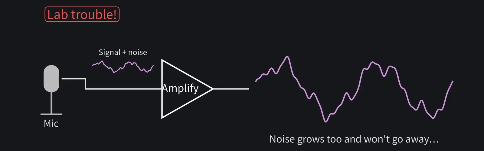
Illustration: Experiment in trouble! I amplified the mic and the noise got louder too, nanoda!
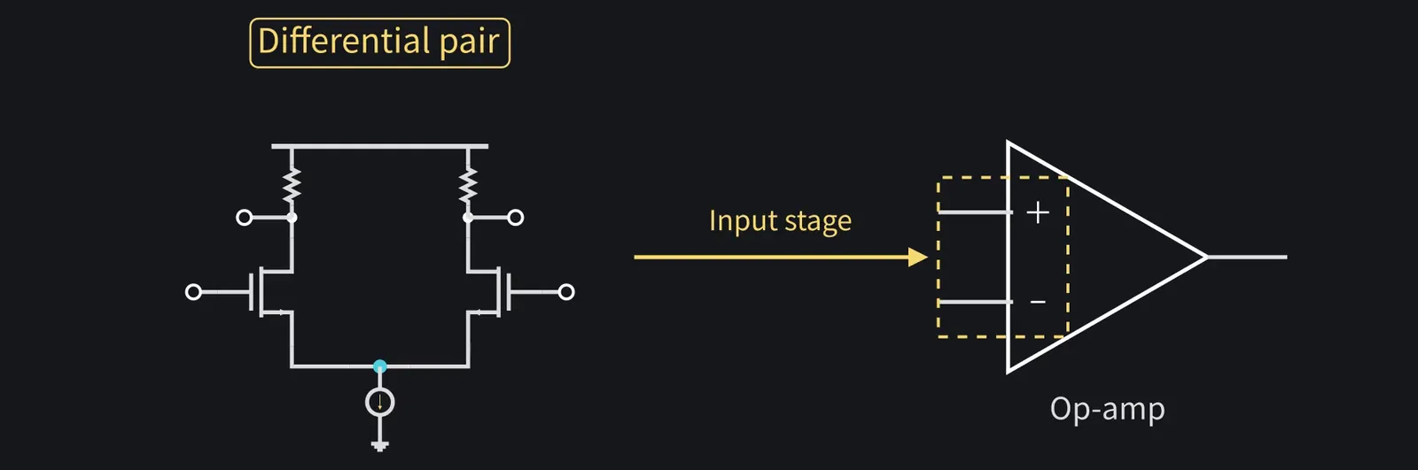
Figure 1

Shikoku Metan

The classic fix is the differential pair. Most op-amp inputs are built this way.

Illustration: The classic fix is the differential pair. Most op-amp inputs are built this way.
Figure 2

Zundamon

Nice to meet you, nanoda! Teach me how to cancel noise, nanoda!

Illustration: Nice to meet you, nanoda! Teach me how to cancel noise, nanoda!
Figure 3

2Why differential signals?

Shikoku Metan

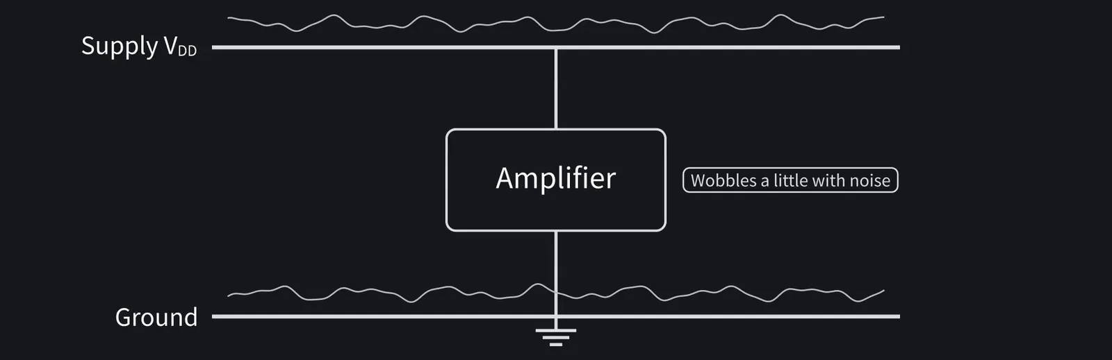
In real circuits, supply and ground voltages wobble a little with noise.

Illustration: In real circuits, supply and ground voltages wobble a little with noise.
Figure 4

Shikoku Metan

In episode four's active-load common-source amp, a 10 mV shift in the input DC moved the output by about 0.35 V.

ZundamonQuestion

What if the source's ground and the amplifier's ground differ by 10 mV, nanoda?
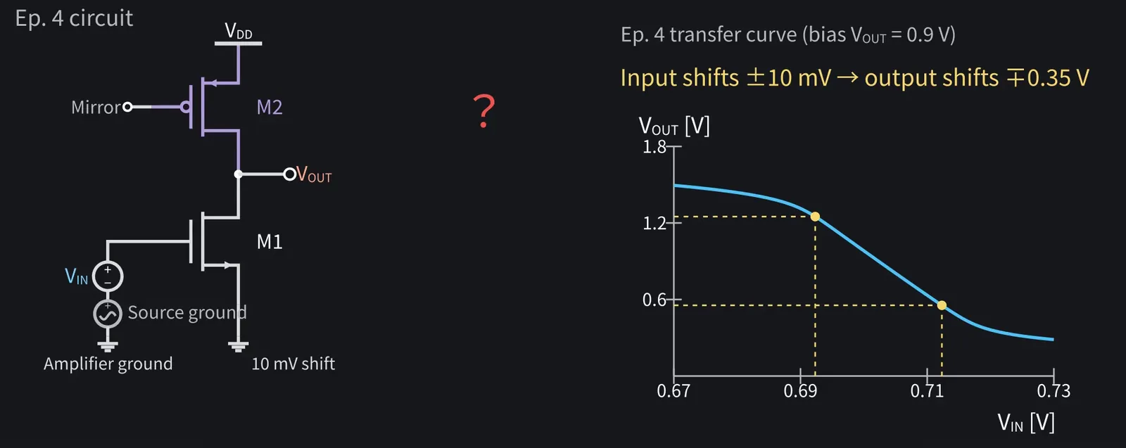
Illustration: What if the source's ground and the amplifier's ground differ by 10 mV, nanoda?
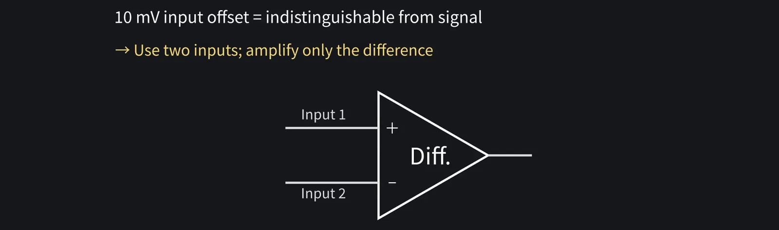
Figure 5

Shikoku Metan

Same as a 10 mV offset at the input. So use two inputs and amplify only the difference.

Illustration: Same as a 10 mV offset at the input. So use two inputs and amplify only the difference.
Figure 6

Shikoku Metan

If the wobble hits both inputs equally, taking the difference cancels it.

Zundamon

Even if both shift by the same amount, the difference stays the same, nanoda!

3The differential-pair circuit
Shikoku Metan

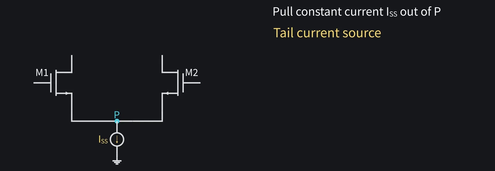
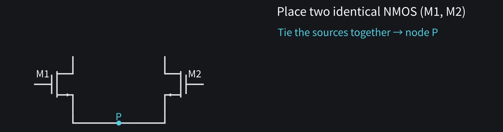
Place two identical NMOS, M1 and M2, and tie their sources together. Call that point P.

Illustration: Place two identical NMOS, M1 and M2, and tie their sources together. Call that point P.
Figure 7

Shikoku Metan

Pull a constant current ISS out of P. We call this the tail current source.

Illustration: Pull a constant current ISS out of P. We call this the tail current source.
Figure 8

Shikoku Metan

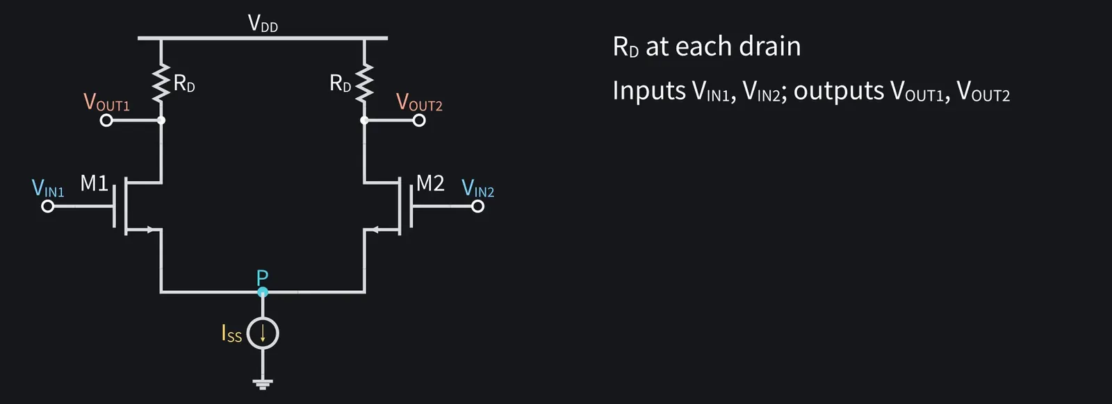
Each drain gets RD. The inputs are VIN1 and VIN2, the outputs VOUT1 and VOUT2.

Illustration: Each drain gets RD. The inputs are VIN1 and VIN2, the outputs VOUT1 and VOUT2.
Figure 9

Shikoku Metan

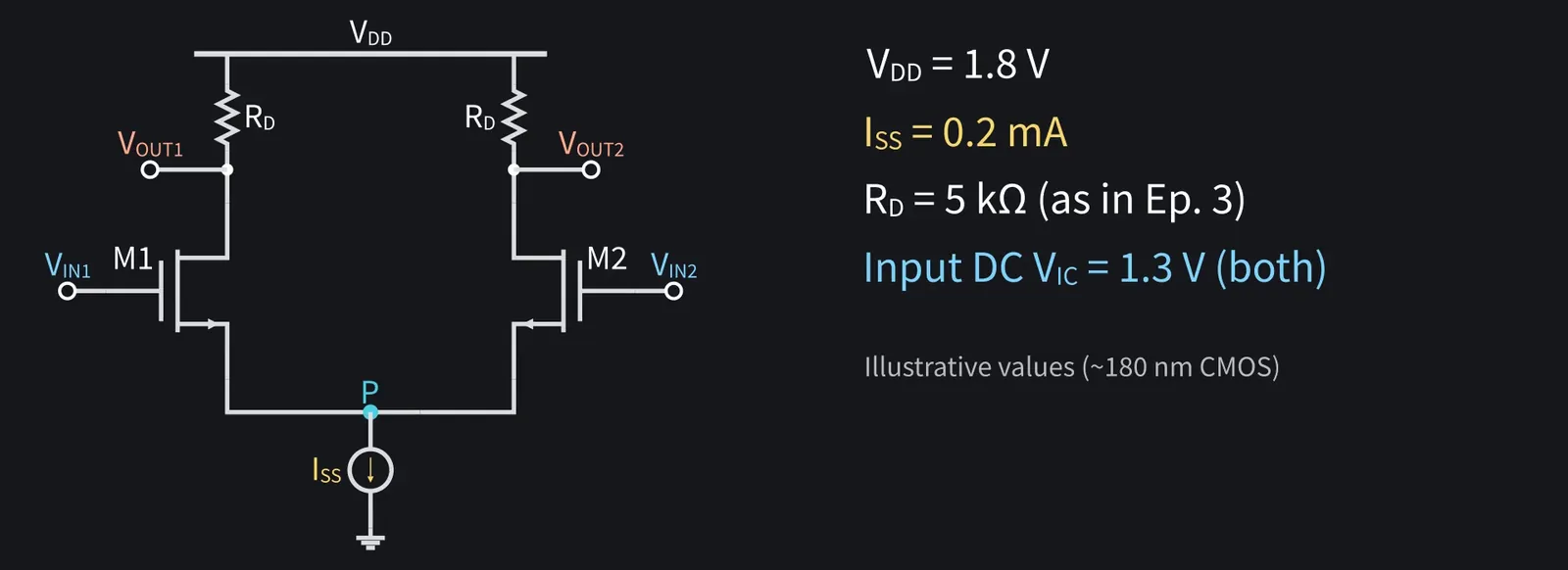
VDD=1.8 V, ISS=0.2 mA, RD=5 kΩ. Both inputs sit at 1.3 V DC.

Illustration: VDD = 1.8 V, ISS = 0.2 mA, RD = 5 kΩ. Both inputs sit at 1.3 V DC.
Figure 10

Shikoku Metan

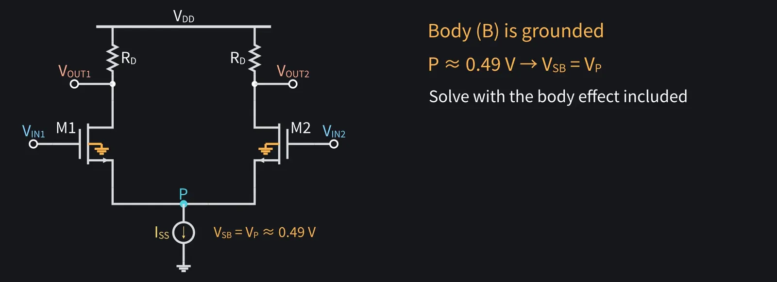
The bodies are grounded. P sits at about 0.49 V, so the sources are not at body potential and we include the body effect.

Illustration: The bodies are grounded. P sits at about 0.49 V, so the sources are not at body potential and we include the body effect.
Figure 11

Shikoku Metan

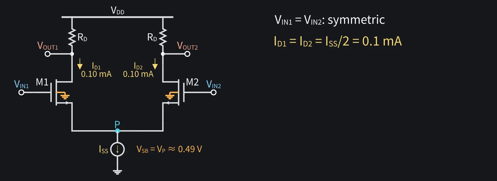
With equal inputs it's symmetric. Each side carries half: 0.1 mA.

Illustration: With equal inputs it's symmetric. Each side carries half: 0.1 mA.
Figure 12

4Large-signal behavior

ZundamonQuestion

What happens if the two inputs differ, nanoda?
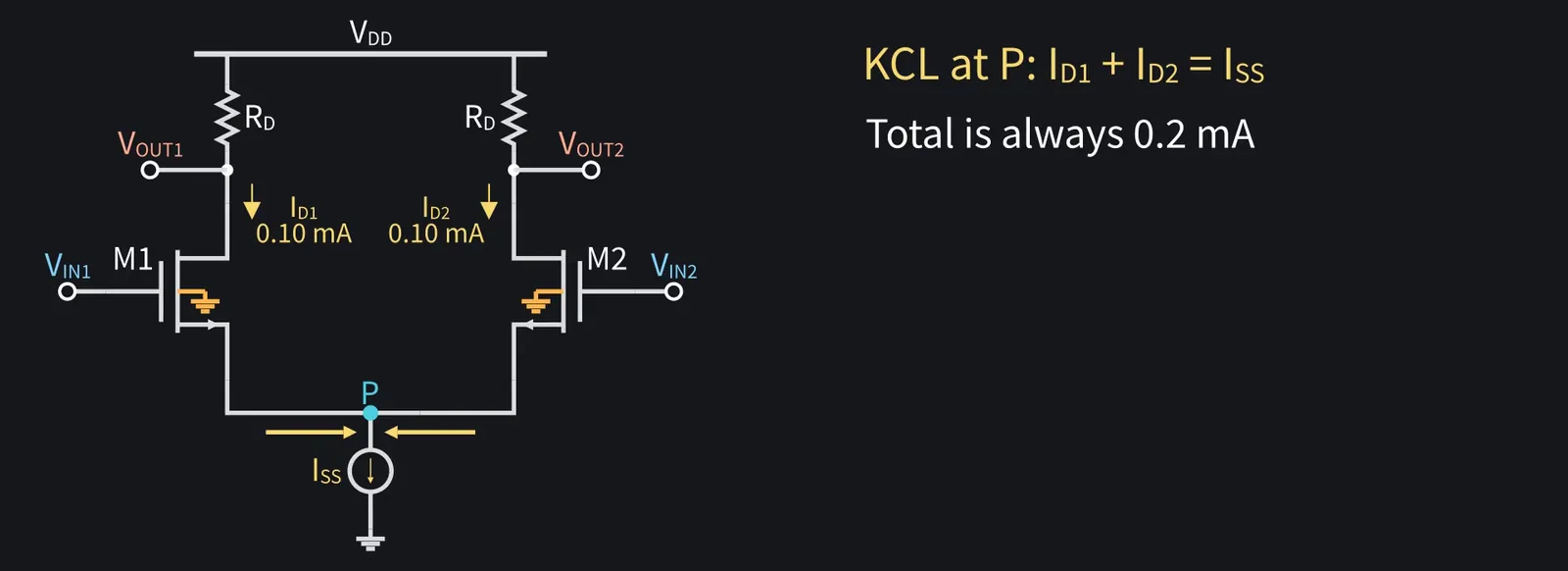
Shikoku Metan

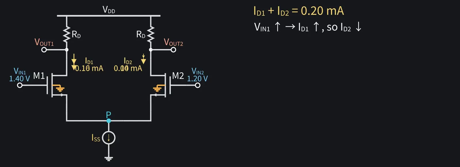
At P, ID1+ID2=ISS. The total is always 0.2 mA.

Illustration: At P, ID1 + ID2 = ISS. The total is always 0.2 mA.
Figure 13

Shikoku Metan

Raise VIN1 and M1 carries more current, so M2 carries less.

Illustration: Raise VIN1 and M1 carries more current, so M2 carries less.
Figure 14

Shikoku Metan

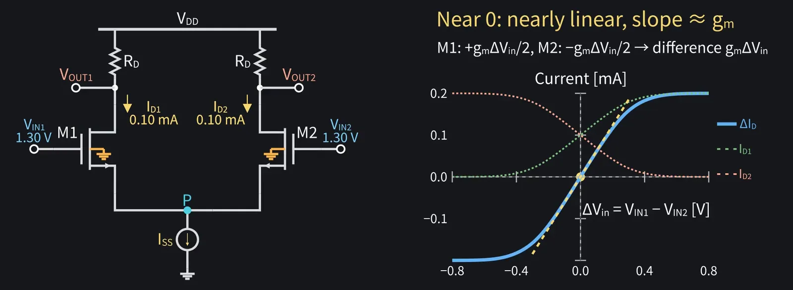
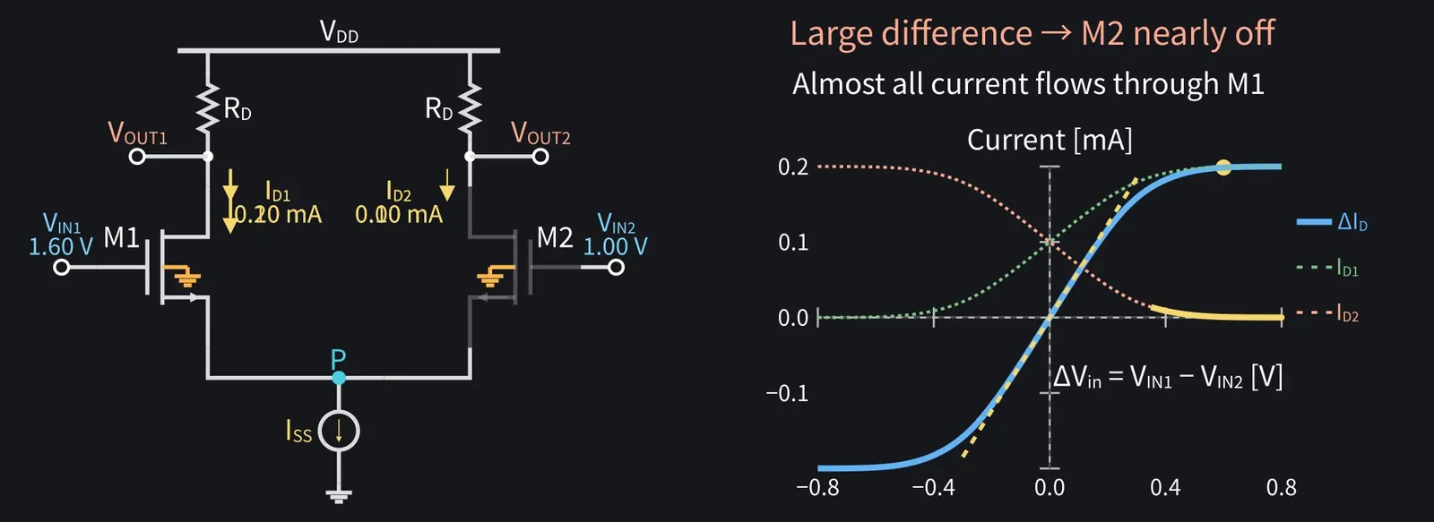
Plot the current difference ΔID=ID1−ID2 against the input difference ΔVin = VIN1−VIN2, and you get the curve in the figure below.

Shikoku Metan: Near zero it's nearly a straight line. M1's current changes by +gm·ΔVin/2 and M2's by −gm·ΔVin/2, so the difference ΔID has a slope of about gm.

Illustration: Near zero it's nearly a straight line. M1's current changes by +gm·ΔVin/2 and M2's by −gm·ΔVin/2, so the difference ΔID has a slope of about gm.
Figure 15

Shikoku Metan

With a large difference, M2 is nearly off. Almost all current flows through M1.

Illustration: With a large difference, M2 is nearly off. Almost all current flows through M1.
Figure 16

Shikoku Metan

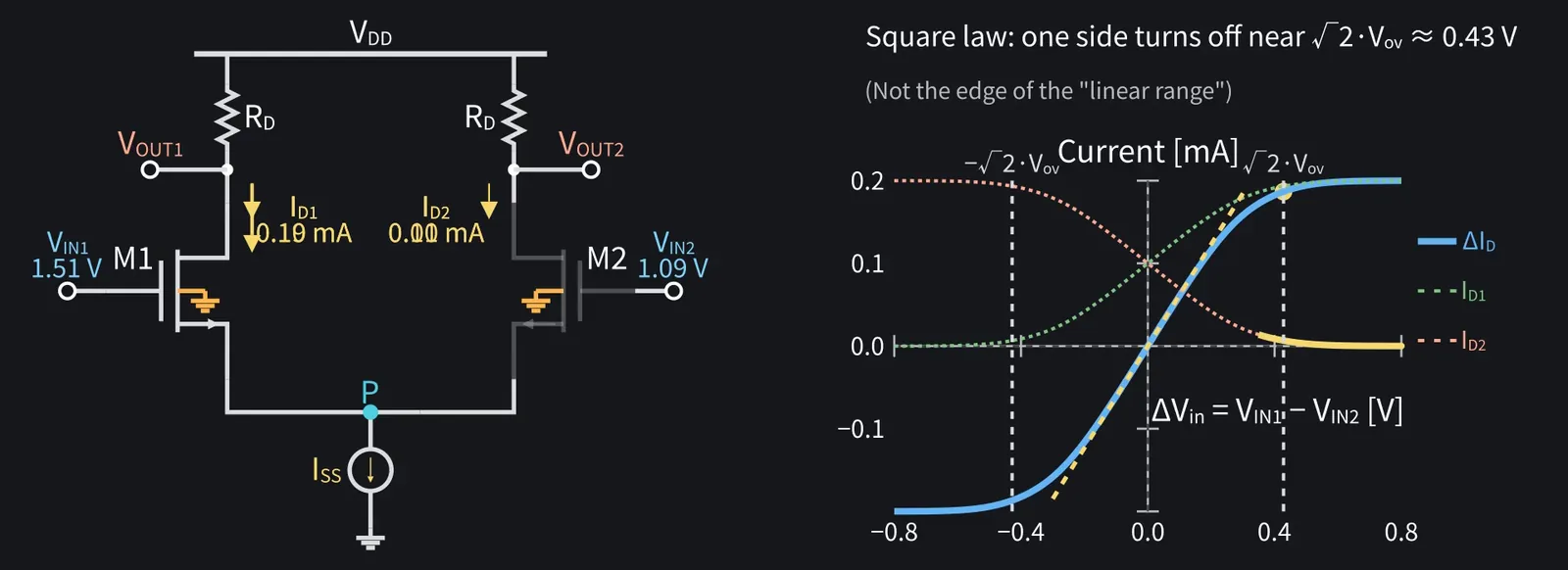
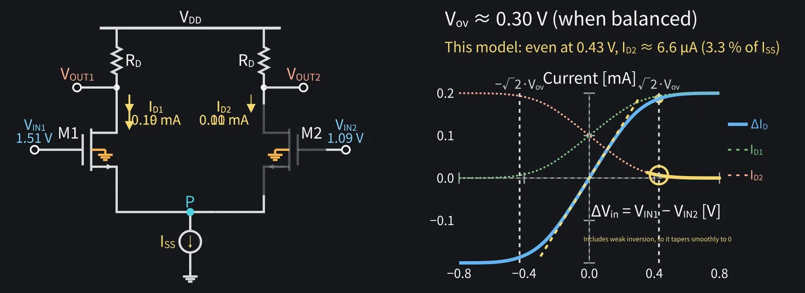
With the square law, one side turns off near √2·Vov, about 0.43 V.

Illustration: With the square law, one side turns off near √2·Vov, about 0.43 V.
Figure 17

Shikoku Metan

Vov is about 0.30 V when balanced. In this model, some current remains at 0.43 V.

Illustration: Vov is about 0.30 V when balanced. In this model, some current remains at 0.43 V.
Figure 18

Zundamon

So with a big difference, it's a switch steering current left or right, nanoda!
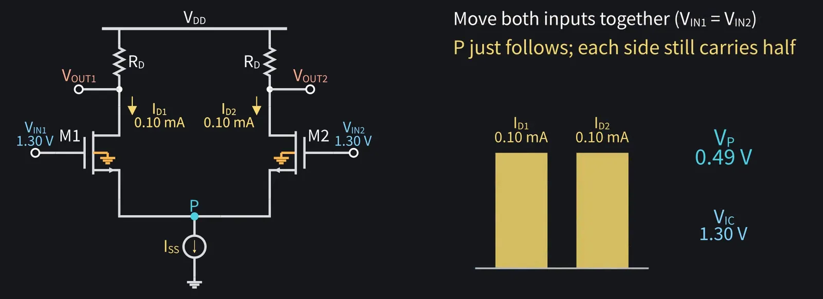
Shikoku Metan

Conversely, move both inputs together and P just follows. Each side still carries half.

Illustration: Conversely, move both inputs together and P just follows. Each side still carries half.
Figure 19

5Differential and common-mode signals
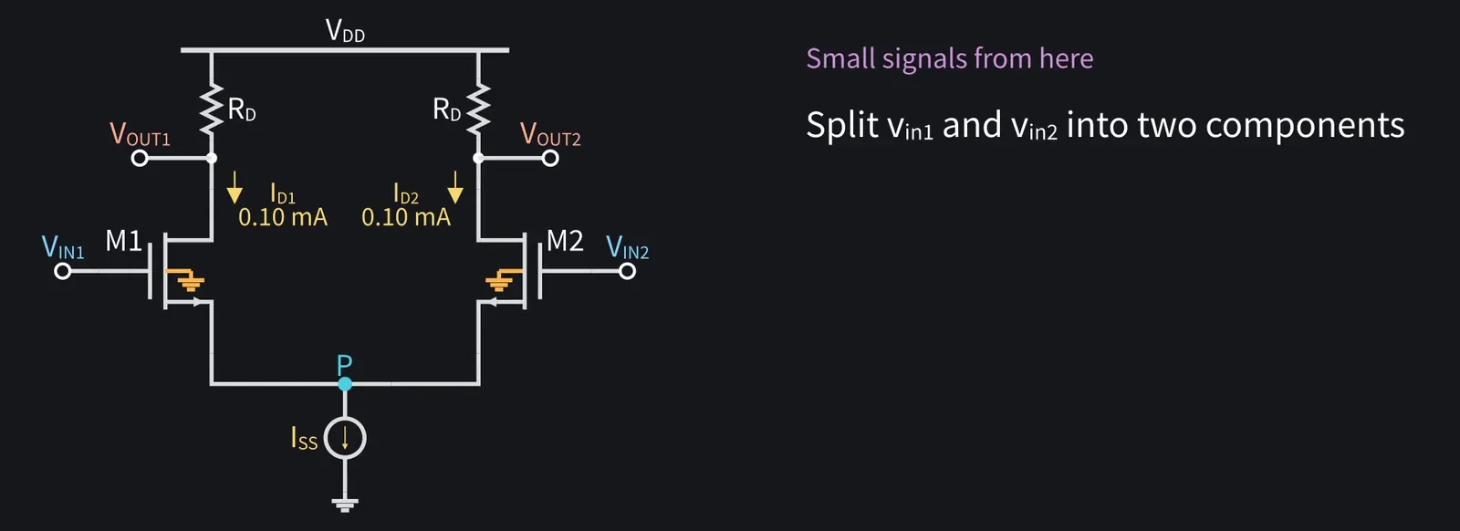
Shikoku Metan

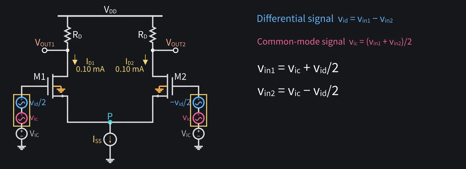
Now small signals. Split inputs vin1 and vin2 into two components.

Illustration: Now small signals. Split inputs vin1 and vin2 into two components.
Figure 20

Shikoku Metan

Differential signal: vid=vin1−vin2. Common-mode signal: vic = (vin1+vin2)/2.

Shikoku Metan: Conversely, vin1=vic+vid/2 and vin2=vic−vid/2.

Illustration: Conversely, vin1 = vic + vid/2 and vin2 = vic − vid/2.
Figure 21

Zundamon

It's a linear circuit, so superposition lets us solve them separately, nanoda!

6Differential half-circuit and gain
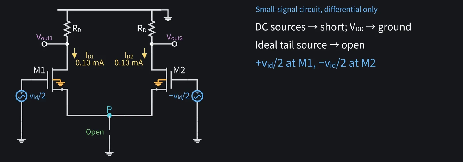
Shikoku Metan

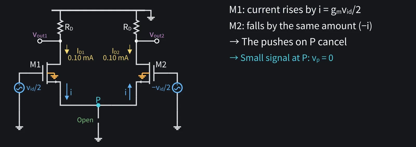
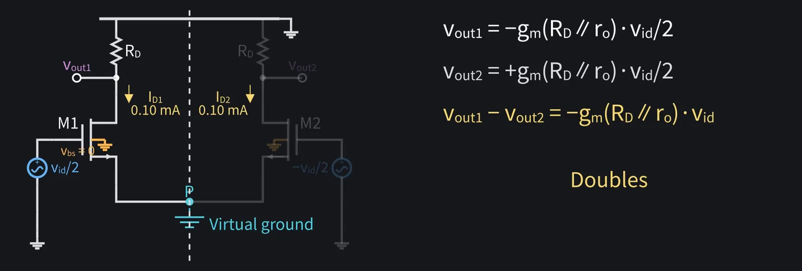
Differential first. M1's gate gets +vid/2 and M2's gate gets −vid/2.

Illustration: Differential first. M1's gate gets +vid/2 and M2's gate gets −vid/2.
Figure 22

Shikoku Metan

The circuit is symmetric and the two inputs are equal and opposite, so their effects on P cancel. P's small-signal voltage is zero.

Illustration: The circuit is symmetric and the two inputs are equal and opposite, so their effects on P cancel. P's small-signal voltage is zero.
Figure 23

Shikoku Metan

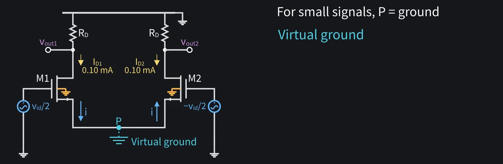
For small signals, P acts like ground. We call this a virtual ground.

Illustration: For small signals, P acts like ground. We call this a virtual ground.
Figure 24

Shikoku Metan

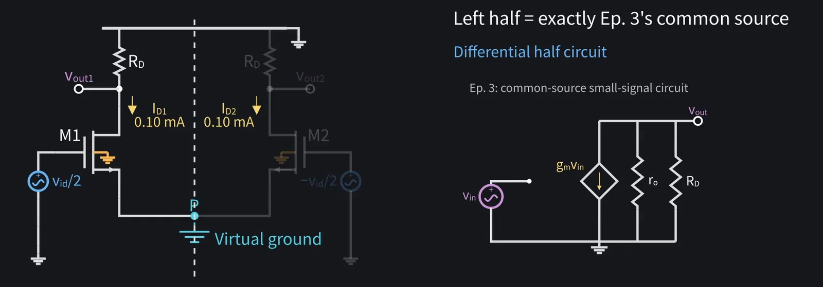
Take the left half on its own: it's exactly episode three's common-source stage. This is the differential half circuit.

Illustration: Take the left half on its own: it's exactly episode three's common-source stage. This is the differential half circuit.
Figure 25

Shikoku Metan

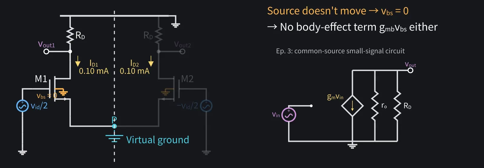
The source doesn't move, so there's no body-effect term either.

Illustration: The source doesn't move, so there's no body-effect term either.
Figure 26

Shikoku Metan

vout1 = −gm(RD∥ro)·vid/2. vout2 has the opposite sign, so the difference doubles.

Illustration: vout1 = −gm(RD∥ro)·vid/2. vout2 has the opposite sign, so the difference doubles.
Figure 27

Shikoku Metan

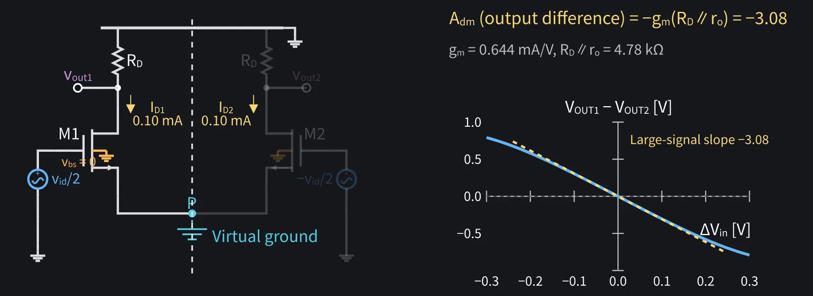
Measured as the output difference, the differential gain is about −3.1: Adm = −gm(RD∥ro). It matches the slope of the large-signal curve near zero.

Illustration: Measured as the output difference, the differential gain is about −3.1: Adm = −gm(RD∥ro). It matches the slope of the large-signal curve near zero.
Figure 28

Zundamon

Even with half the input each, the difference gives one common-source gain, nanoda!

7Common-mode half-circuit and gain
Shikoku Metan

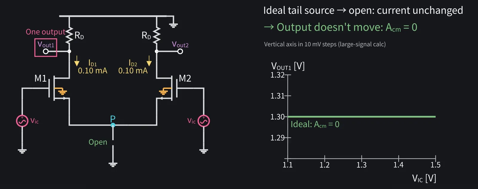
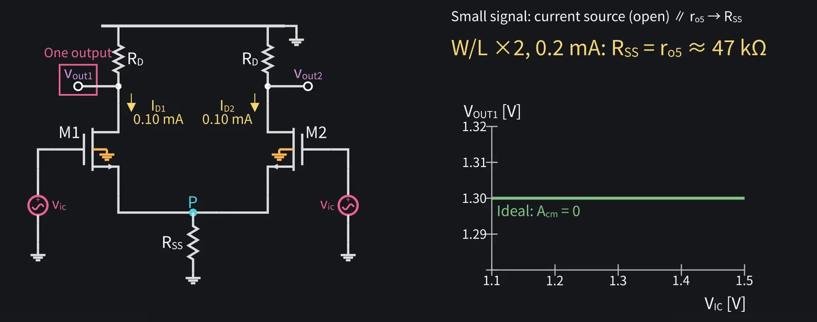
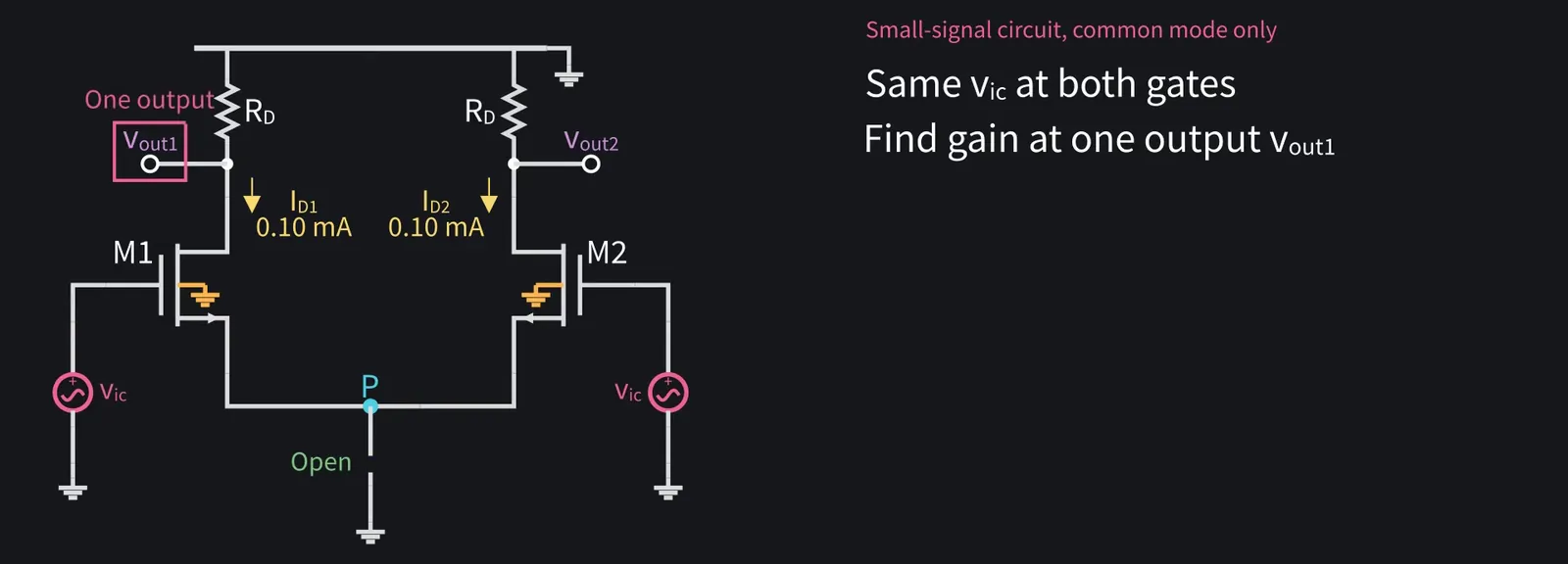
Next, common mode. Same vic at both gates, gain measured at one output.

Illustration: Next, common mode. Same vic at both gates, gain measured at one output.
Figure 29

Shikoku Metan

With an ideal tail source, current can't change, the output stays put, so Acm=0.

Illustration: With an ideal tail source, current can't change, the output stays put, so Acm = 0.
Figure 30

Shikoku Metan

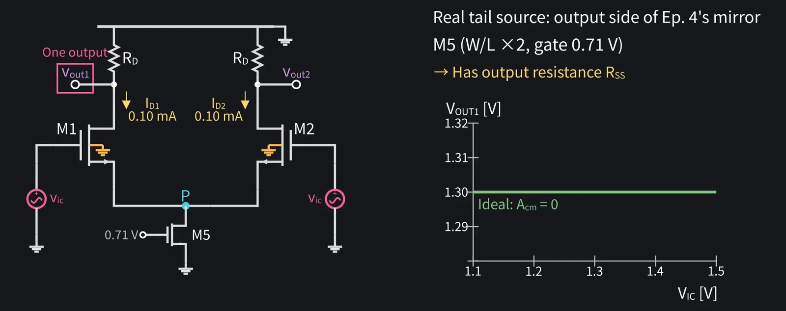
But a real tail source is episode four's mirror, with output resistance RSS.

Illustration: But a real tail source is episode four's mirror, with output resistance RSS.
Figure 31

Shikoku Metan

Call the tail-current NMOS M5. With W/L twice episode four's and 0.2 mA flowing, RSS is M5's ro, about 47 kΩ.

Illustration: Call the tail-current NMOS M5. With W/L twice episode four's and 0.2 mA flowing, RSS is M5's ro, about 47 kΩ.
Figure 32

Shikoku Metan

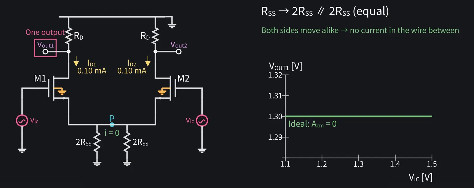
Replace RSS with two resistors of 2·RSS in parallel. By symmetry, no current flows in the wire joining them.

Illustration: Replace RSS with two resistors of 2·RSS in parallel. By symmetry, no current flows in the wire joining them.
Figure 33

Shikoku Metan

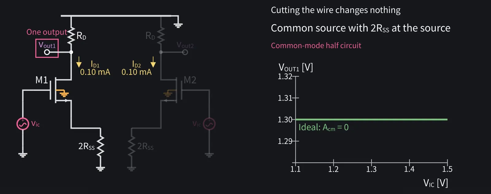
Cut that wire, and each side is a common-source stage with 2·RSS at its source. That's the common-mode half circuit.

Illustration: Cut that wire, and each side is a common-source stage with 2·RSS at its source. That's the common-mode half circuit.
Figure 34

ZundamonQuestion

What happens when the source has a resistor, nanoda?
Shikoku Metan

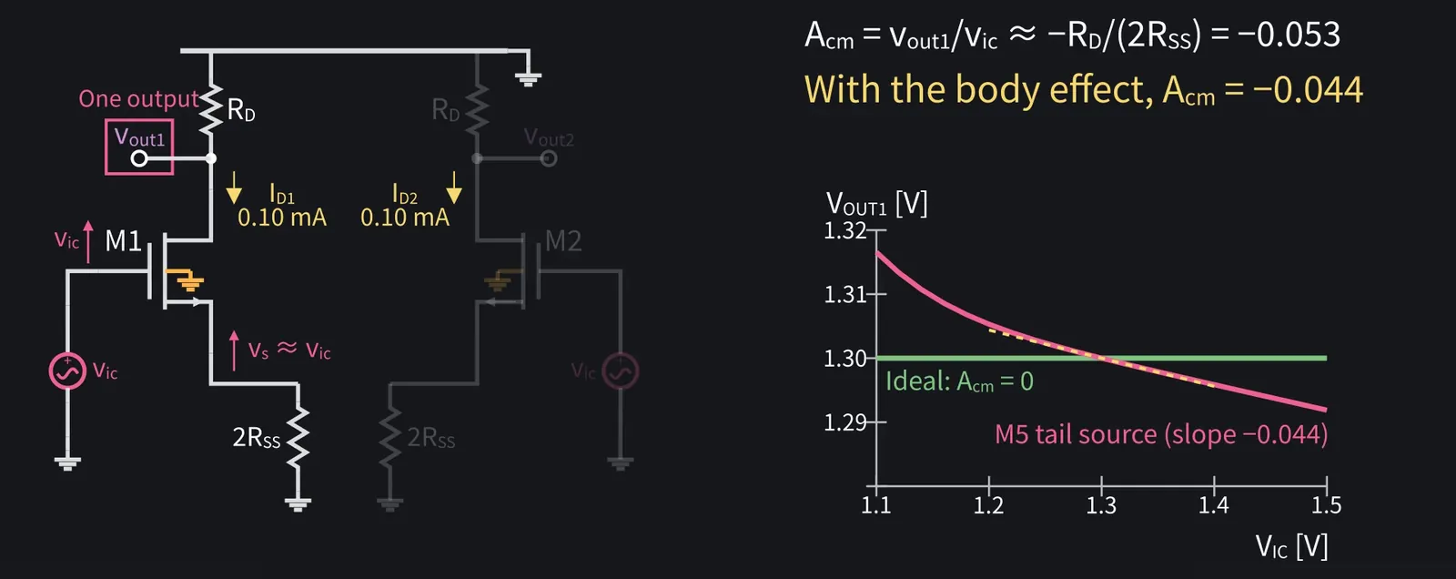
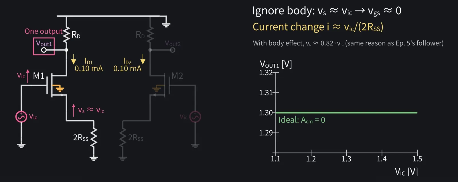
Ignoring the body effect, the source rises by the same vic as the gate. So the current through 2·RSS, which is the drain current, changes by only vic/(2·RSS).

Illustration: Ignoring the body effect, the source rises by the same vic as the gate. So the current through 2·RSS, which is the drain current, changes by only vic/(2·RSS).
Figure 35

Shikoku Metan

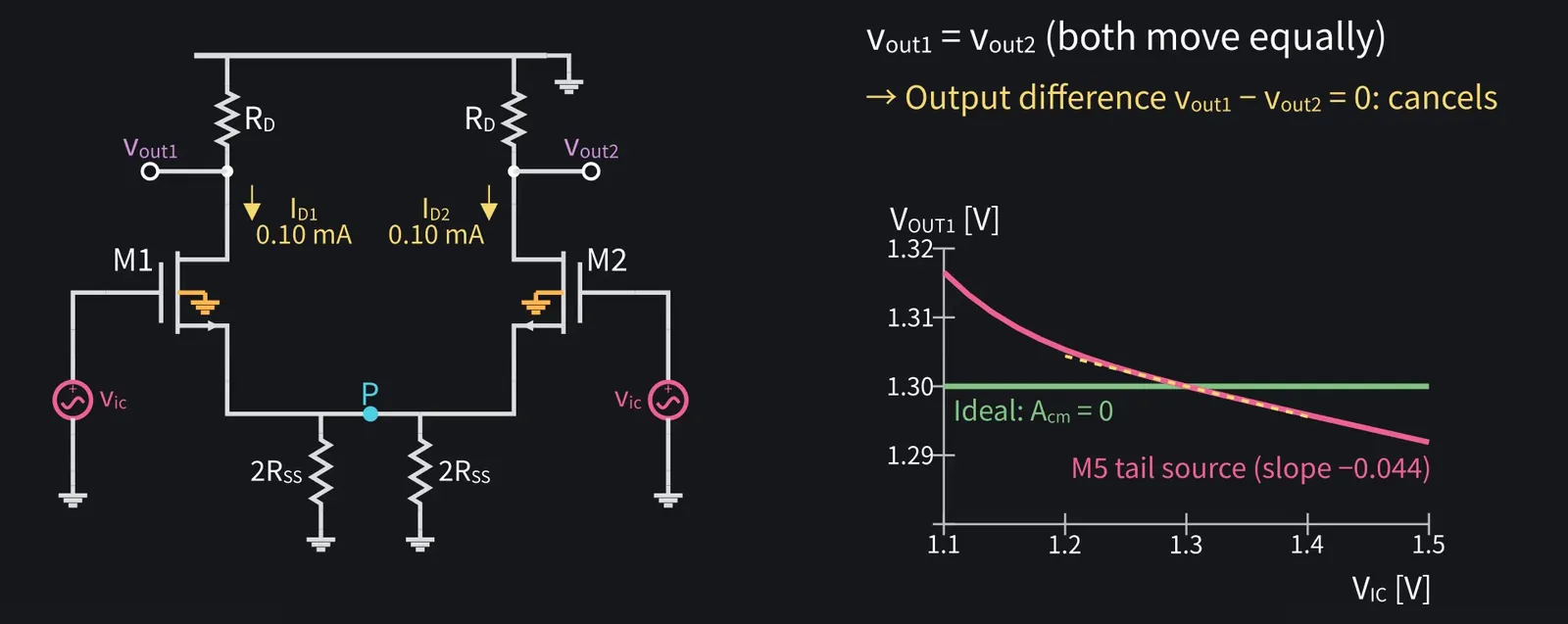
So Acm ≈ −RD/(2·RSS), about −0.053. Including the body effect, it's about −0.044.

Illustration: So Acm ≈ −RD/(2·RSS), about −0.053. Including the body effect, it's about −0.044.
Figure 36

Shikoku Metan

Both outputs move equally, so taking their difference cancels it completely.

Illustration: Both outputs move equally, so taking their difference cancels it completely.
Figure 37

8Common-mode rejection ratio (CMRR)
Shikoku Metan

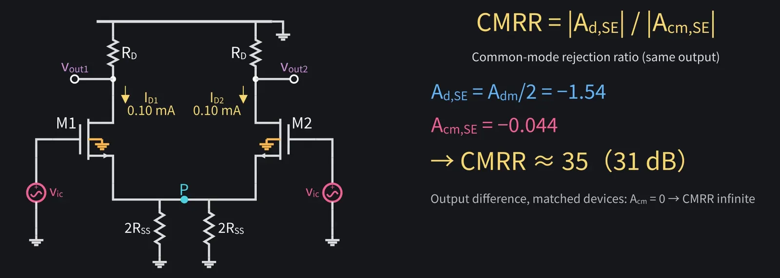
The ratio of differential to common-mode gain at the same output is the CMRR.

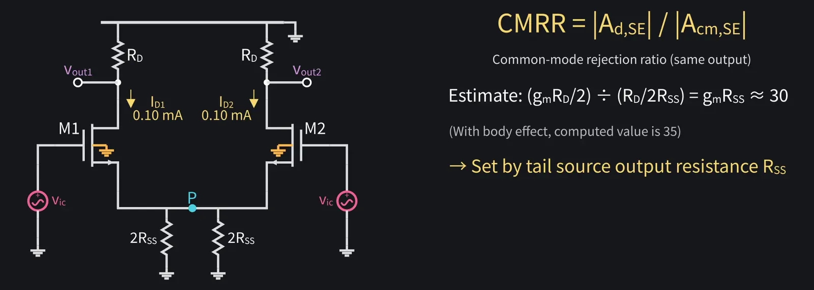
Shikoku Metan: At one output, differential gain is half: about 1.5. CMRR is about 35.

Illustration: At one output, differential gain is half: about 1.5. CMRR is about 35.
Figure 38

Shikoku Metan

Ignoring the body effect, the estimate is (gm·RD/2) ÷ (RD/(2·RSS)) = gm·RSS, about 30. The tail source's output resistance sets it.

Illustration: Ignoring the body effect, the estimate is (gm·RD/2) ÷ (RD/(2·RSS)) = gm·RSS, about 30. The tail source's output resistance sets it.
Figure 39

Shikoku Metan

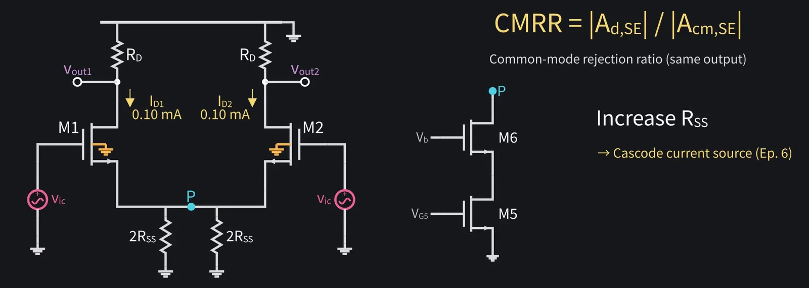
To go higher, raise RSS. That's where episode six's cascode current source comes in.

Illustration: To go higher, raise RSS. That's where episode six's cascode current source comes in.
Figure 40

Shikoku Metan

But a cascode tail source needs more voltage headroom, so the input DC level has to be set higher.

9The active-load differential pair

ZundamonQuestion

How do we hand the output to the next stage on a single wire, nanoda?
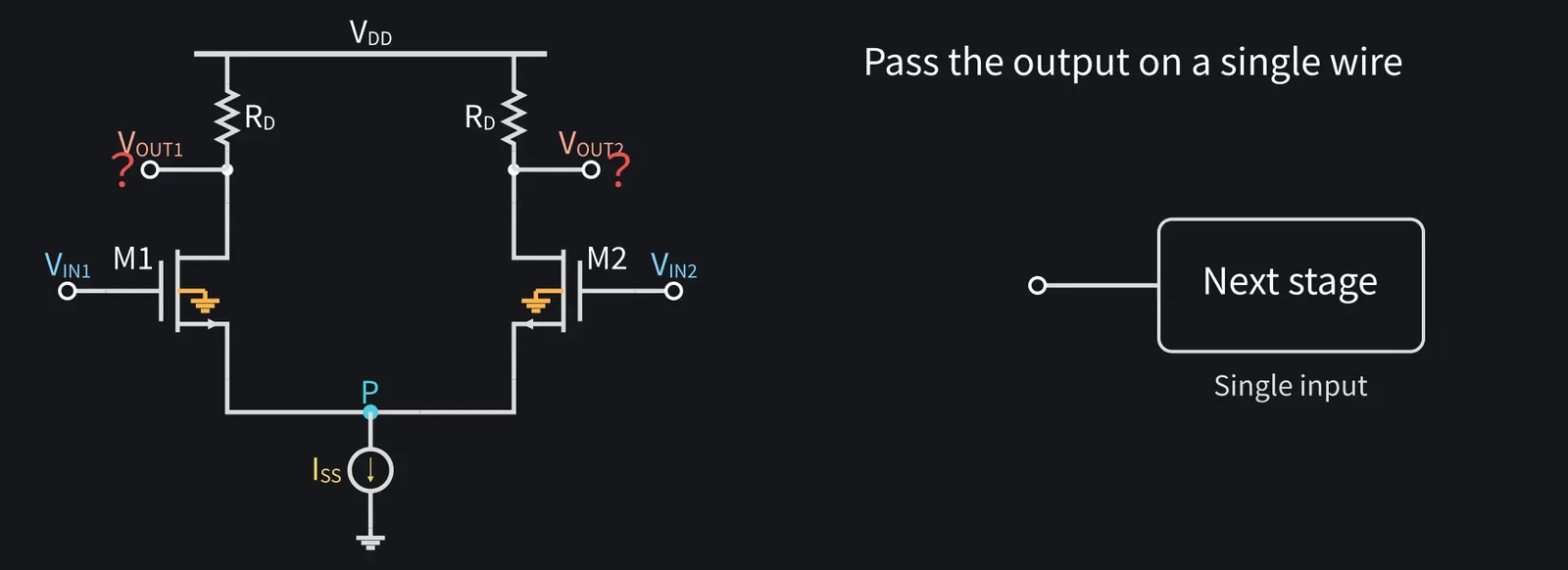
Illustration: How do we hand the output to the next stage on a single wire, nanoda?
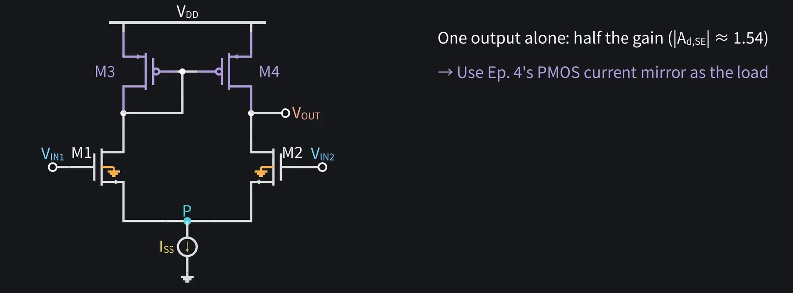
Figure 41

Shikoku Metan

One side alone gives half the gain. So use episode four's PMOS mirror as the load.

Illustration: One side alone gives half the gain. So use episode four's PMOS mirror as the load.
Figure 42

Shikoku Metan

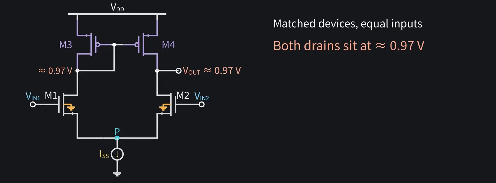
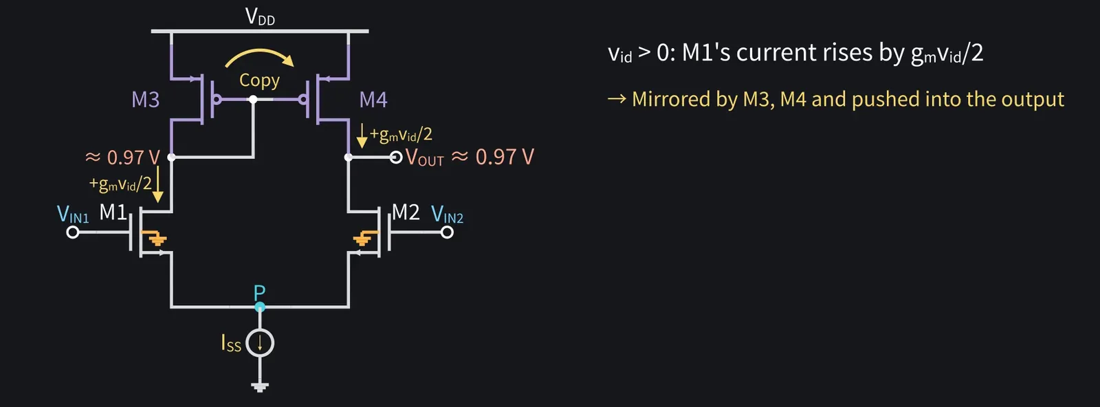
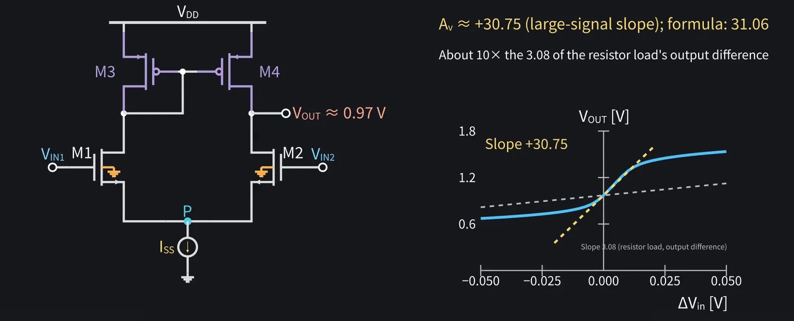
M3 takes M1's current and M4 copies it. The output is the drains of M2 and M4.

Shikoku Metan: With matched devices and equal inputs, both drains sit at VDD minus M3's VSG of about 0.83 V: about 0.97 V.

Illustration: With matched devices and equal inputs, both drains sit at VDD minus M3's VSG of about 0.83 V: about 0.97 V.
Figure 43

Shikoku Metan

When vid raises M1's current, M4 copies it and pushes current into the output.

Illustration: When vid raises M1's current, M4 copies it and pushes current into the output.
Figure 44

Shikoku Metan

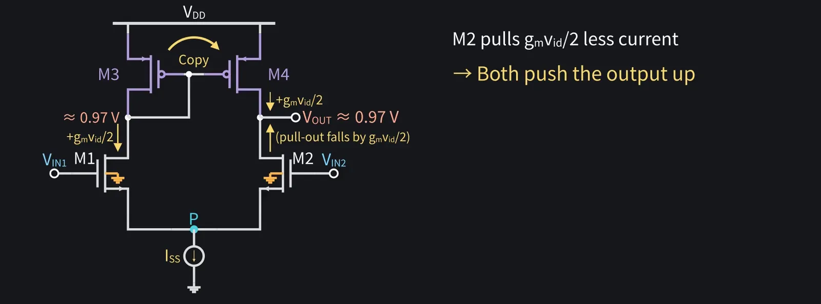
At the same time, M2 pulls less current. Both push the output up.

Illustration: At the same time, M2 pulls less current. Both push the output up.
Figure 45

Shikoku Metan

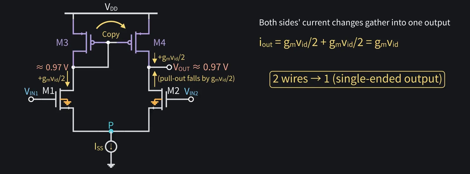
The current changes from both sides are collected at one output: differential-to-single-ended conversion.

Illustration: The current changes from both sides are collected at one output: differential-to-single-ended conversion.
Figure 46

Shikoku Metan

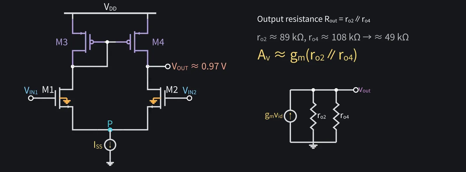
The current changes from both sides add up to gm·vid at the output, and the resistance seen there is ro2∥ro4. So the gain is Av≈gm(ro2∥ro4).

Illustration: The current changes from both sides add up to gm·vid at the output, and the resistance seen there is ro2∥ro4. So the gain is Av ≈ gm(ro2∥ro4).
Figure 47

Zundamon

It's the same form as episode four's active load, nanoda!
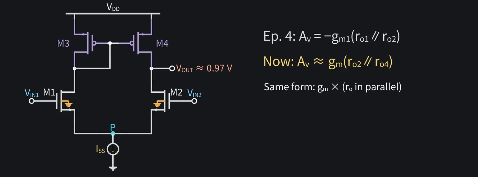
Illustration: It's the same form as episode four's active load, nanoda!
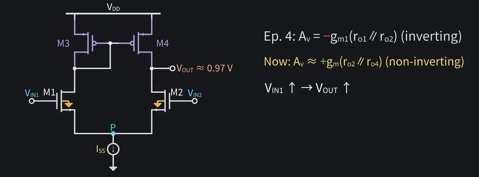
Figure 48

Shikoku Metan

Yes. But unlike episode four, it's non-inverting. Raise VIN1 and the output rises.

Illustration: Yes. But unlike episode four, it's non-inverting. Raise VIN1 and the output rises.
Figure 49

Shikoku Metan

The gain is about +31, roughly 10 times the resistor-load difference gain.

Illustration: The gain is about +31, roughly 10 times the resistor-load difference gain.
Figure 50

Shikoku Metan

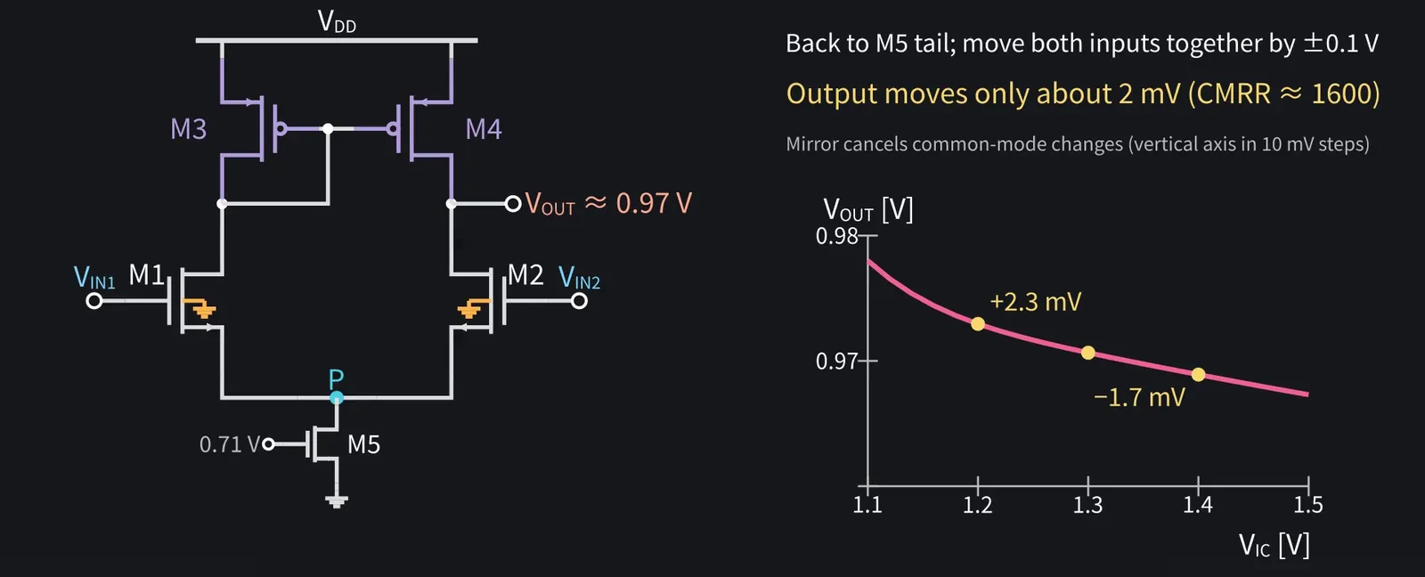
Even when both currents change equally, the part M4 copies and M2's own change cancel at the output. With the M5 tail source, moving both inputs together by 0.1 V shifts the output only about 2 mV.

Illustration: Even when both currents change equally, the part M4 copies and M2's own change cancel at the output. With the M5 tail source, moving both inputs together by 0.1 V shifts the output only about 2 mV.
Figure 51

ZundamonQuestion

Does that also fix episode four's drifting operating point, nanoda?
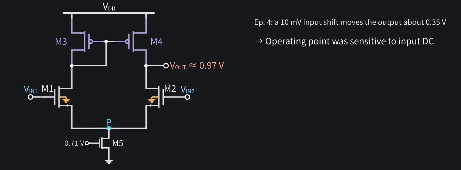
Illustration: Does that also fix episode four's drifting operating point, nanoda?
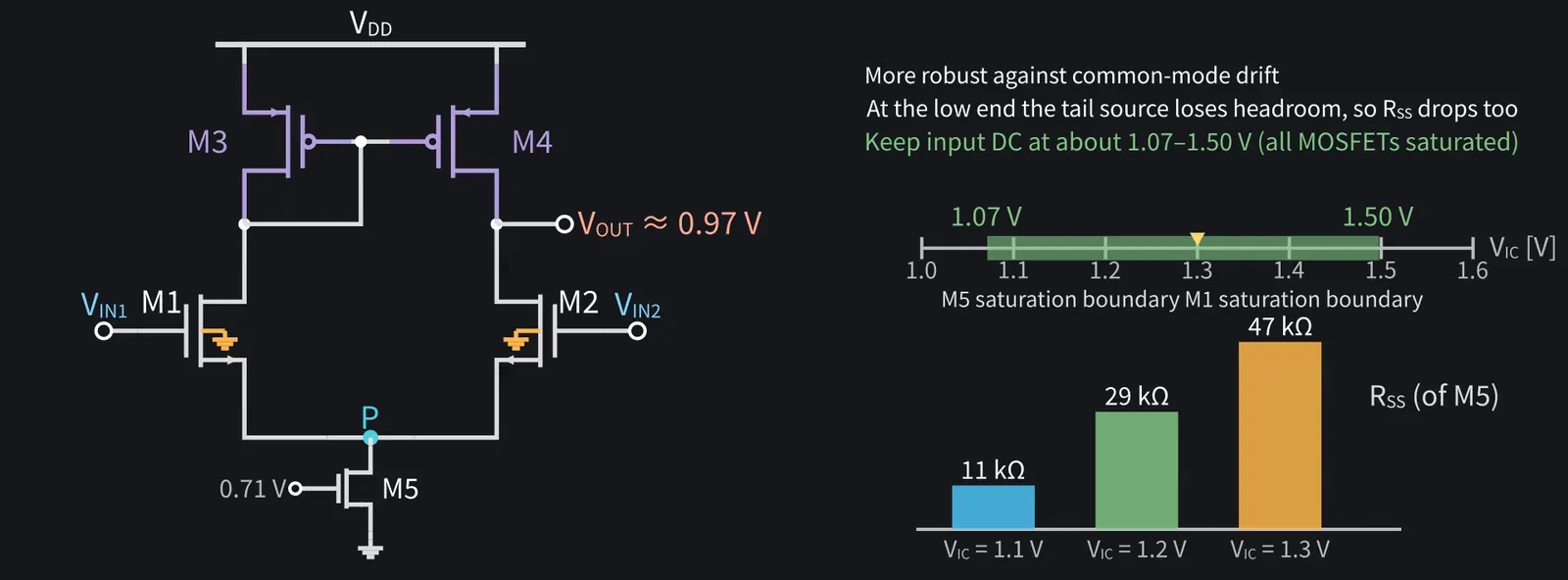
Figure 52

Shikoku Metan

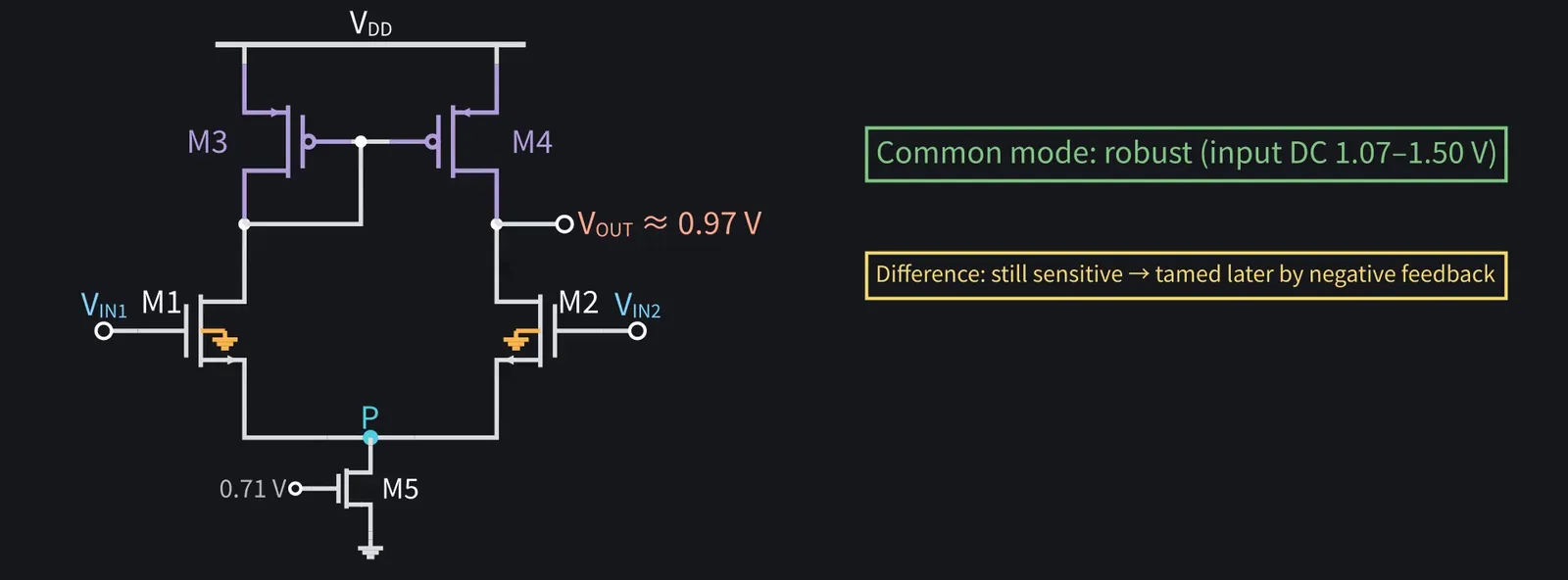
It's more robust against common-mode drift. But the input DC level still has to stay within about 1.07 to 1.50 V.

Shikoku Metan: At the low end, the tail source M5 runs out of drain-voltage headroom and RSS drops. At the high end, M1's drain runs out of headroom.

Illustration: At the low end, the tail source M5 runs out of drain-voltage headroom and RSS drops. At the high end, M1's drain runs out of headroom.
Figure 53

Shikoku Metan

It's still sensitive to the difference between the two inputs. We'll tame that later with negative feedback.

Illustration: It's still sensitive to the difference between the two inputs. We'll tame that later with negative feedback.
Figure 54

10Summary

Shikoku Metan

To sum up: a tail source fixes the total current; the pair amplifies only the difference.

Zundamon

With an active load there's one output, and the gain is gm(ro∥ro), nanoda!
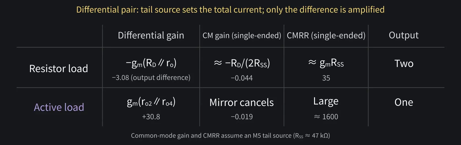
Illustration: With an active load there's one output, and the gain is gm(ro∥ro), nanoda!
Figure 55

Zundamon

Noise that hits both inputs equally cancels in the difference, nanoda! How that differs from using one output goes in my report too!
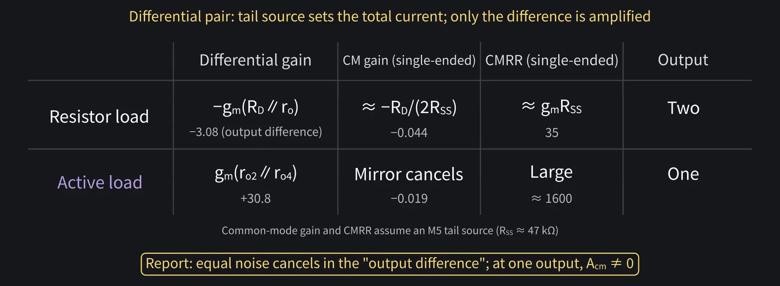
Illustration: Noise that hits both inputs equally cancels in the difference, nanoda! How that differs from using one output goes in my report too!
Figure 56

Shikoku Metan

Next time: an introduction to op-amps. Today's differential pair is what's inside that triangle symbol.

Zundamon

Thanks for reading, nanoda!