Learn Analog Circuits with Zundamon

Episode 5

Source Followers and Common-Gate Amplifiers

Connecting a load can drastically reduce gain. Explore the source follower and common-gate stage, and compare the three basic amplifier configurations.

Watch on YouTube (6:41)
  • Shikoku Metan (explains)
  • Zundamon (asks)

1Intro: the load makes the gain collapse

Zundamon

My experiment's in trouble! Adding a load made the amplifier gain collapse!
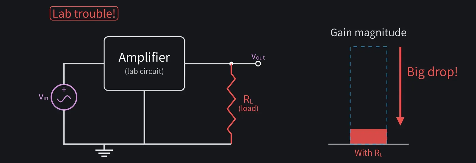
Illustration: My experiment's in trouble! Adding a load made the amplifier gain collapse!
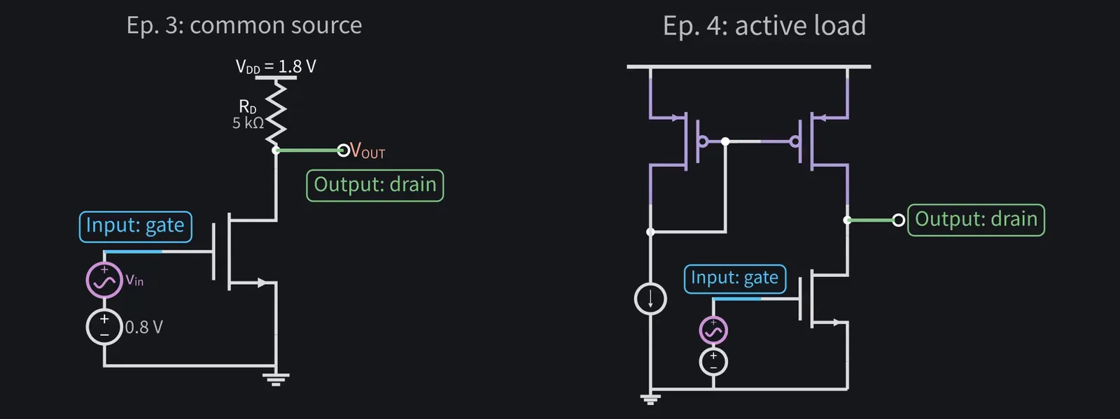
Figure 1

Shikoku Metan

So far, every stage took input at the gate and output at the drain.

Illustration: So far, every stage took input at the gate and output at the drain.
Figure 2

Shikoku Metan

Where the signal goes in and comes out changes the behavior. Today we compare the three basic amplifier stages.

Illustration: Where the signal goes in and comes out changes the behavior. Today we compare the three basic amplifier stages.
Figure 3

Zundamon

Please! I want a circuit that can handle a load, nanoda!

Illustration: Please! I want a circuit that can handle a load, nanoda!
Figure 4

2Three ways to connect a MOSFET

Shikoku Metan

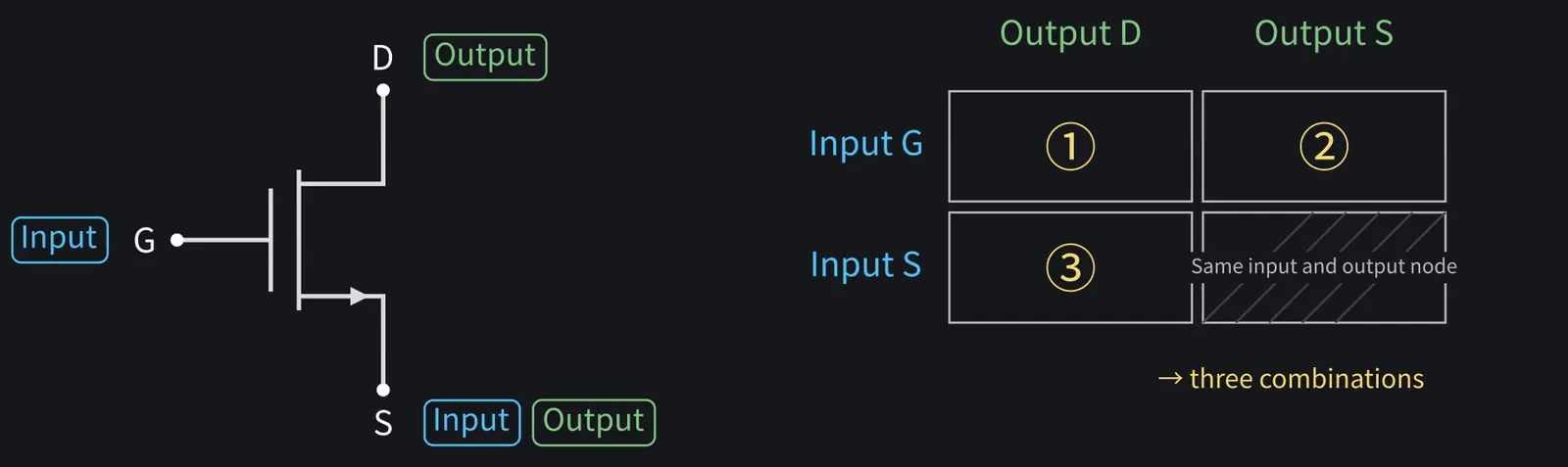
The input goes to the gate or the source, and the output comes from the drain or the source. Input and output can't share a terminal, so that leaves three combinations.

Illustration: The input goes to the gate or the source, and the output comes from the drain or the source. Input and output can't share a terminal, so that leaves three combinations.
Figure 5

Shikoku Metan

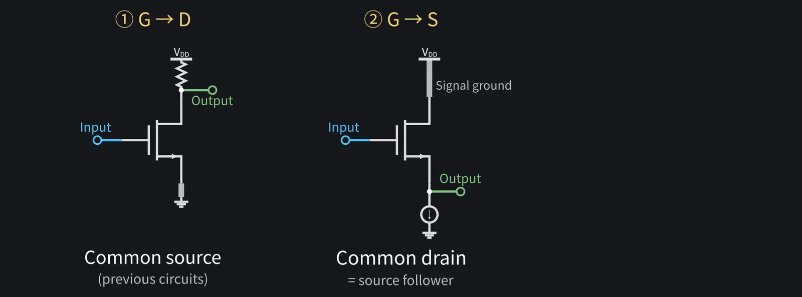
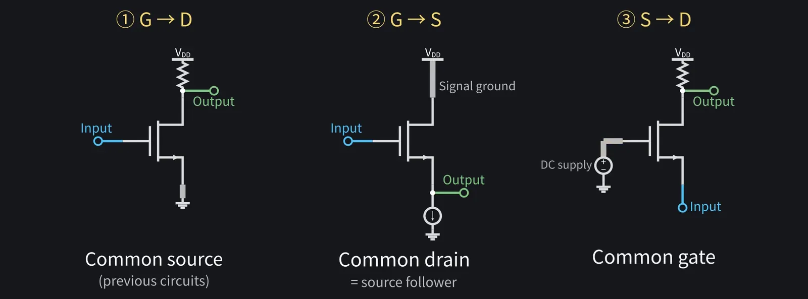
Gate in, drain out: that's the common-source stage we've used.

Shikoku Metan: Gate in, source out: common drain, also called a source follower.

Illustration: Gate in, source out: common drain, also called a source follower.
Figure 6

Shikoku Metan

Source in, drain out: that's common gate.

Illustration: Source in, drain out: that's common gate.
Figure 7

Shikoku Metan

"Common" means the remaining terminal is at ground in the small-signal circuit.

ZundamonQuestion

Why not put the input at the drain?
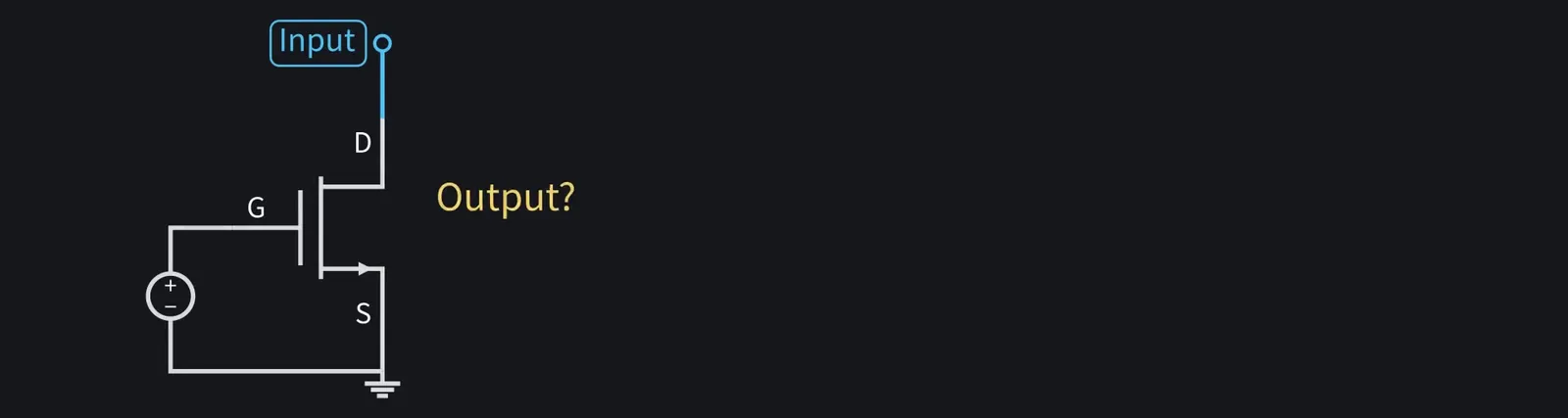
Illustration: Why not put the input at the drain?
Figure 8

Shikoku Metan

In saturation, drain voltage barely changes current, making it a poor input.

3Source follower: large-signal behavior
Shikoku Metan

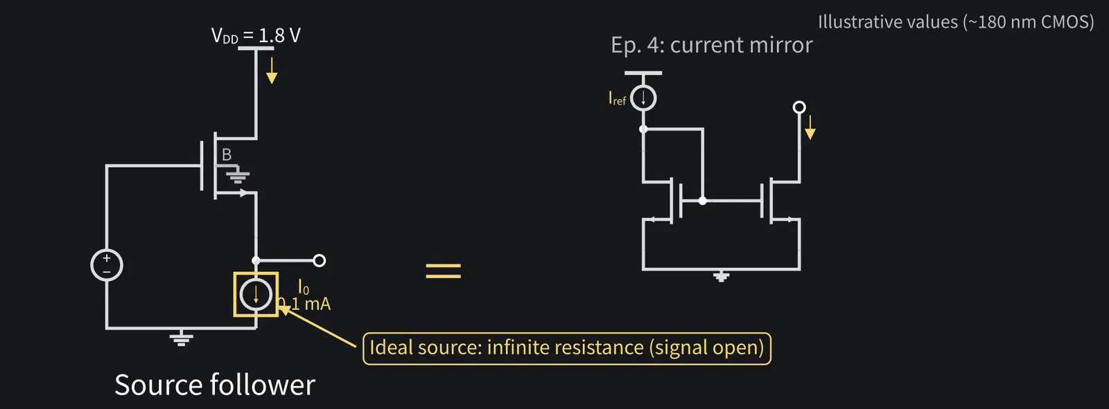
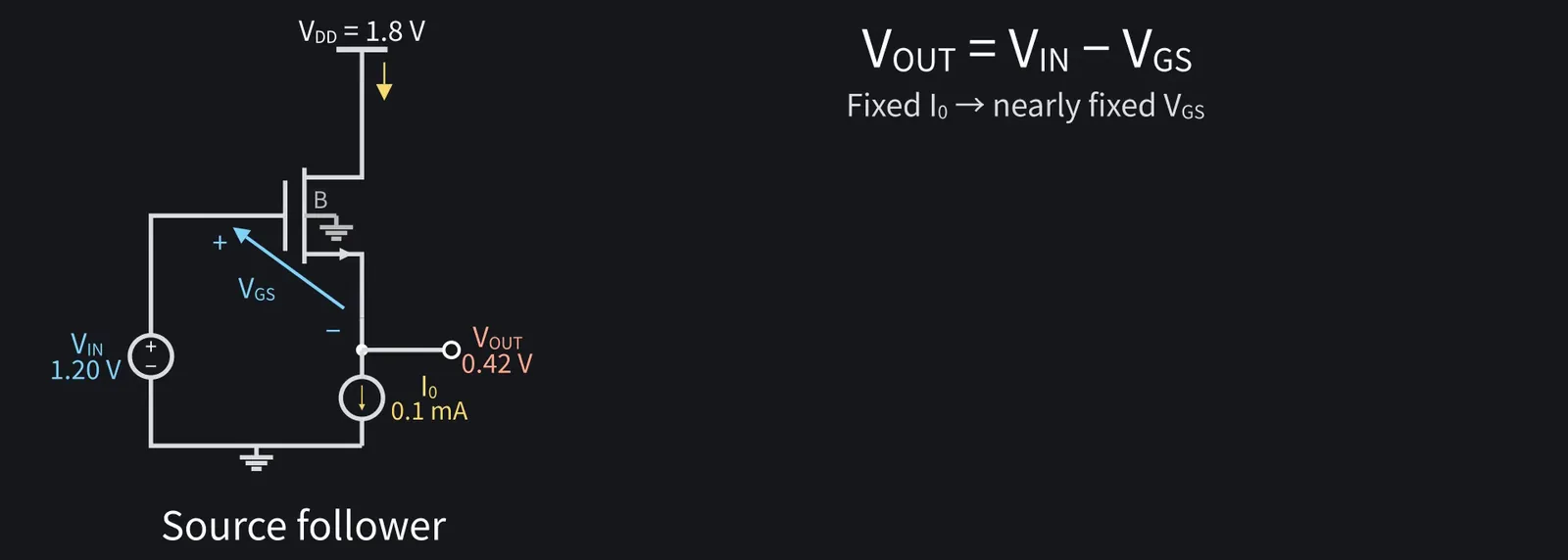
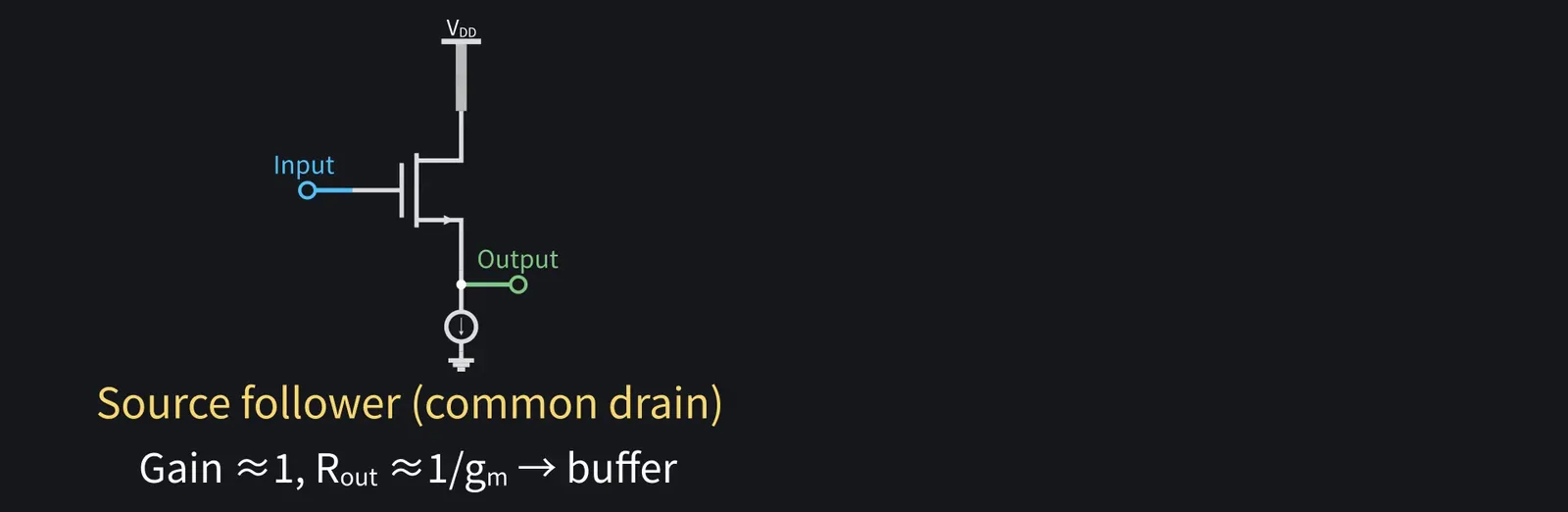
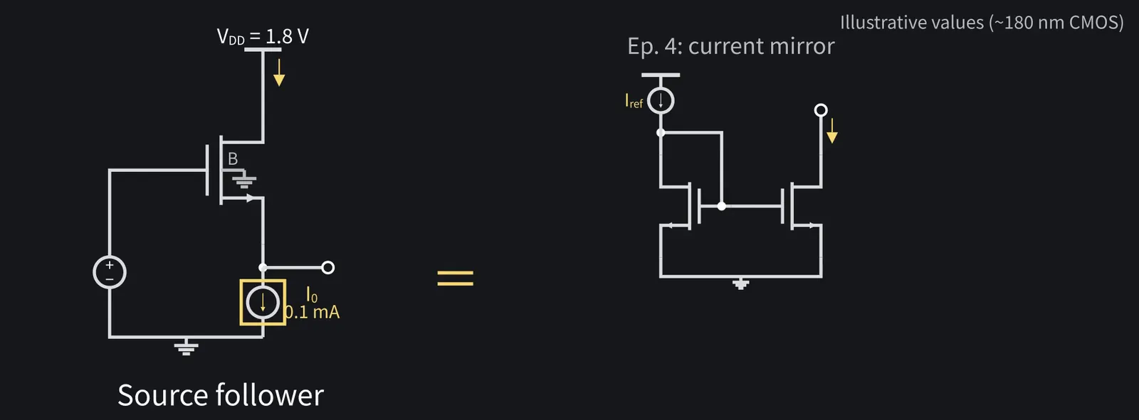
First, the source follower. Drain to VDD, with a current sink at the source.

Shikoku Metan: VDD=1.8 V and I0=0.1 mA. Episode four's mirror could provide the current.

Illustration: VDD = 1.8 V and I0 = 0.1 mA. Episode four's mirror could provide the current.
Figure 9

Shikoku Metan

For this calculation, though, use an ideal sink with infinite output resistance.

Illustration: For this calculation, though, use an ideal sink with infinite output resistance.
Figure 10

Shikoku Metan

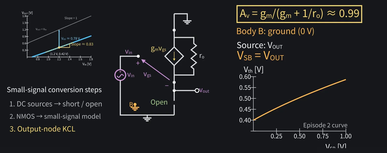
Fixed current nearly fixes VGS, so VOUT=VIN−VGS.

Illustration: Fixed current nearly fixes VGS, so VOUT = VIN − VGS.
Figure 11

Zundamon

On the graph, VOUT follows just below VIN!
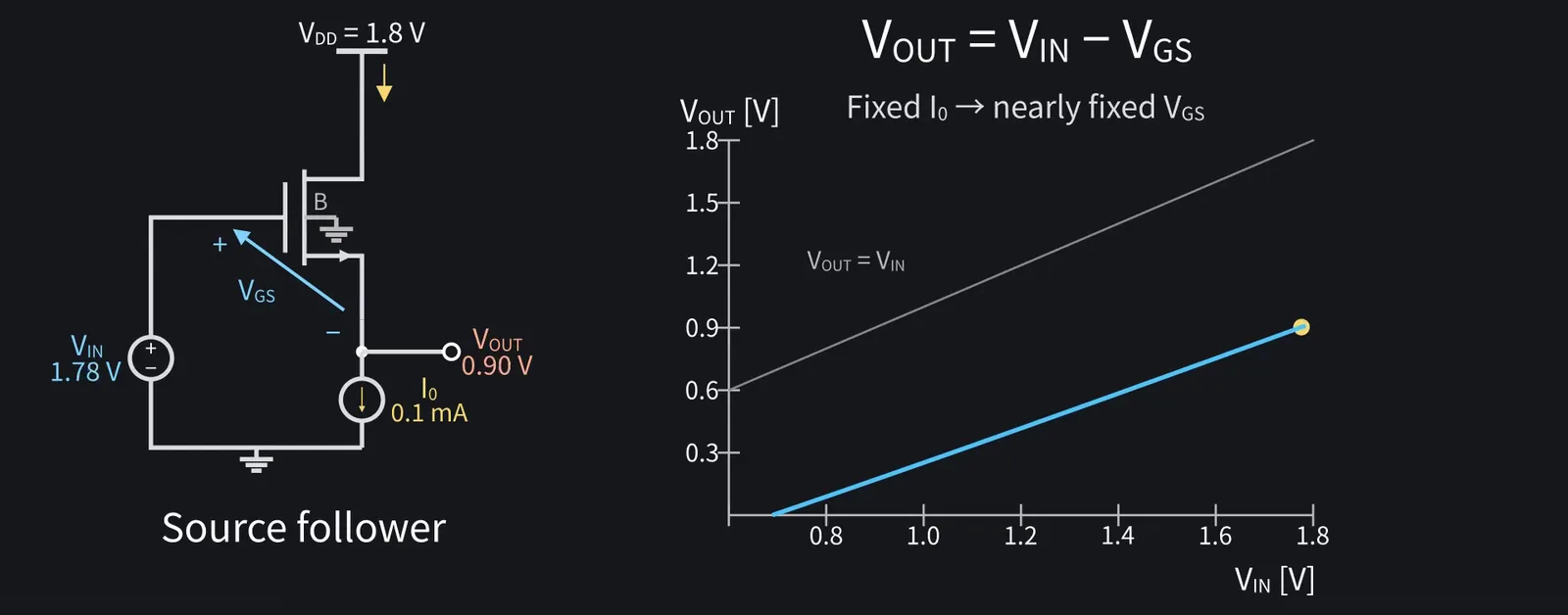
Illustration: On the graph, VOUT follows just below VIN!
Figure 12

Shikoku Metan

That's why it's a follower. At VIN=1.2 V, VOUT is about 0.42 V.

Shikoku Metan: DC shifts down by VGS≈0.78 V, but changes pass through almost unchanged.

ZundamonQuestion

Is the slope exactly one?

Shikoku Metan

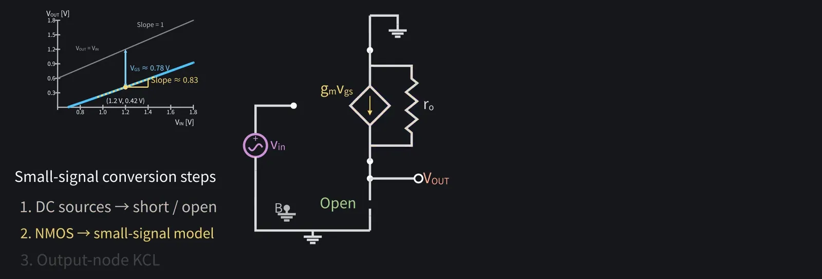
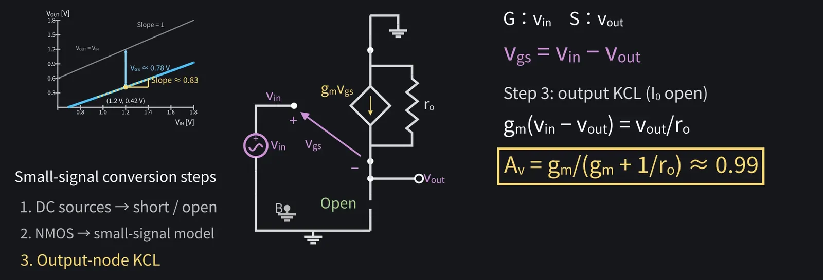
Measuring the slope on the graph gives about 0.83, a little less than one. Let's see why with the small-signal circuit.

4Source follower: small-signal gain and body effect
Shikoku Metan

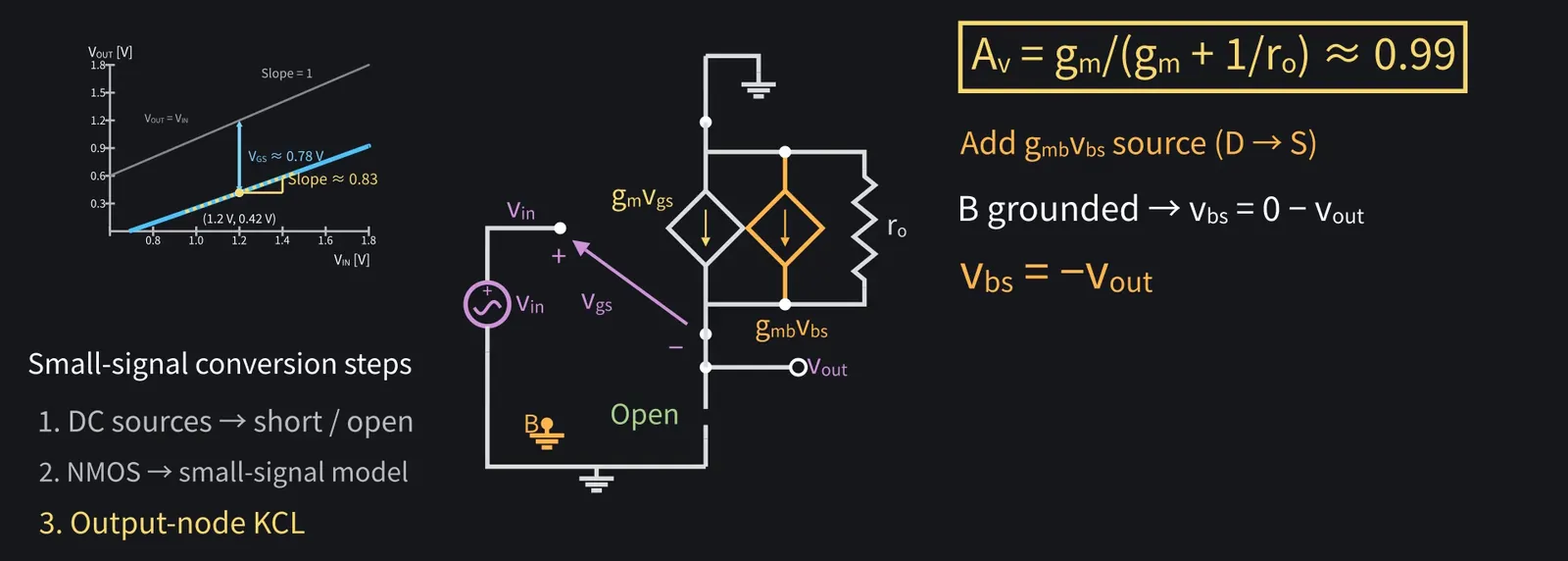
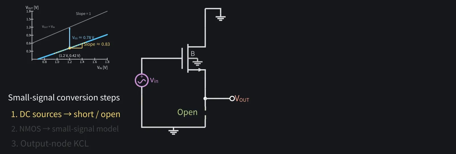
Step one: short the DC supply VDD and open the ideal current source. With VDD shorted, the drain is at signal ground.

Illustration: Step one: short the DC supply VDD and open the ideal current source. With VDD shorted, the drain is at signal ground.
Figure 13

Shikoku Metan

Step two: replace the MOSFET with its small-signal model.

Illustration: Step two: replace the MOSFET with its small-signal model.
Figure 14

Shikoku Metan

The gate has vin and source vout, so vgs=vin−vout.

Shikoku Metan: Step three: KCL at the output, gm(vin−vout) = vout/ro, gives Av=vout/vin=gm/(gm+1/ro), about 0.99.

Illustration: Step three: KCL at the output, gm(vin − vout) = vout/ro, gives Av = vout/vin = gm/(gm + 1/ro), about 0.99.
Figure 15

ZundamonQuestion

But the graph gave 0.83. What's missing?
Shikoku Metan

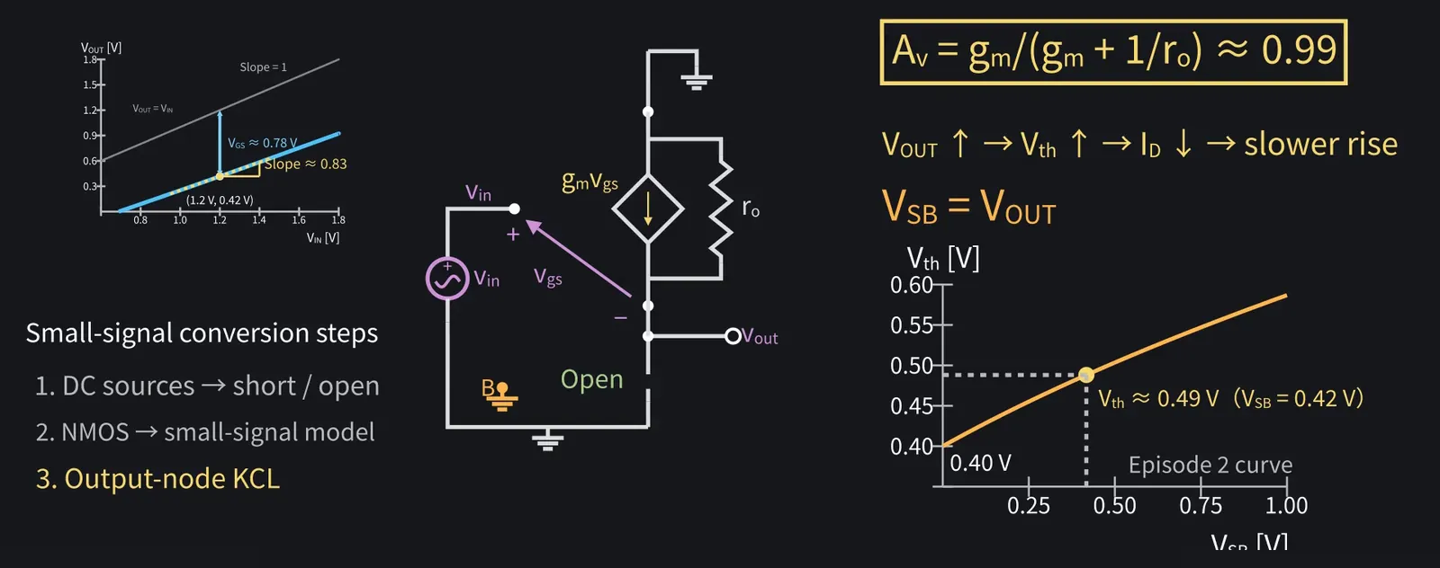
Episode two's body effect. Body at ground and source at VOUT means VSB=VOUT.

Illustration: Episode two's body effect. Body at ground and source at VOUT means VSB = VOUT.
Figure 16

Shikoku Metan

As the output rises, Vth rises too, so passing the same I0 takes a larger VGS. That's why the output rises less than the input.

Illustration: As the output rises, Vth rises too, so passing the same I0 takes a larger VGS. That's why the output rises less than the input.
Figure 17

Shikoku Metan

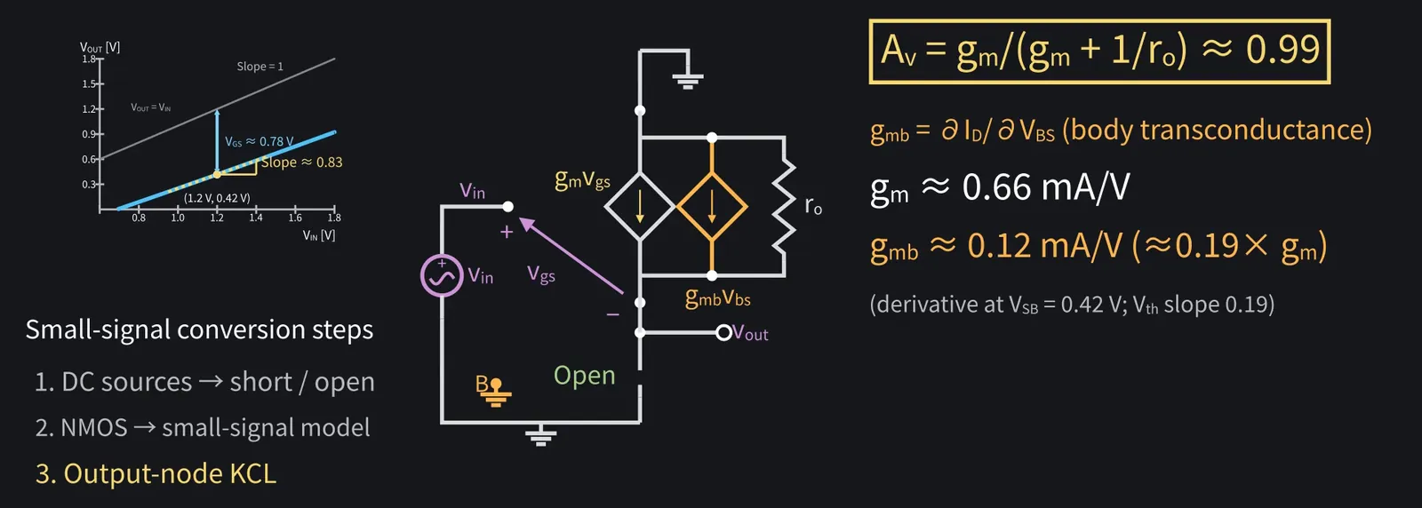
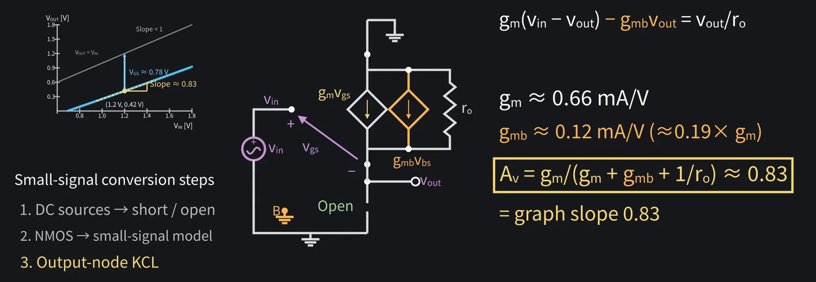
In the small-signal model, add a second current source gmb·vbs beside gm·vgs, where vbs is the small-signal body-source voltage. The body is grounded, so vbs = −vout.

Illustration: In the small-signal model, add a second current source gmb·vbs beside gm·vgs, where vbs is the small-signal body-source voltage. The body is grounded, so vbs = −vout.
Figure 18

Shikoku Metan

gmb is body transconductance. Here gm≈0.66 mA/V and gmb is about 20% of it.

Illustration: gmb is body transconductance. Here gm ≈ 0.66 mA/V and gmb is about 20% of it.
Figure 19

Shikoku Metan

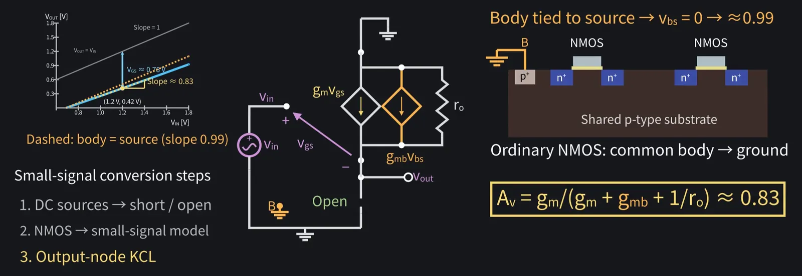
Av=gm/(gm+gmb+1/ro) ≈ 0.83, matching the graph.

Illustration: Av = gm/(gm + gmb + 1/ro) ≈ 0.83, matching the graph.
Figure 20

Shikoku Metan

Tying the body to the source restores about 0.99, but in an ordinary NMOS the body is the p-substrate shared by the whole chip, and it's tied to ground.

Illustration: Tying the body to the source restores about 0.99, but in an ordinary NMOS the body is the p-substrate shared by the whole chip, and it's tied to ground.
Figure 21

Zundamon

So episode two's body effect matters here!

5Source-follower output resistance

ZundamonQuestion

What use is a stage with gain below one?
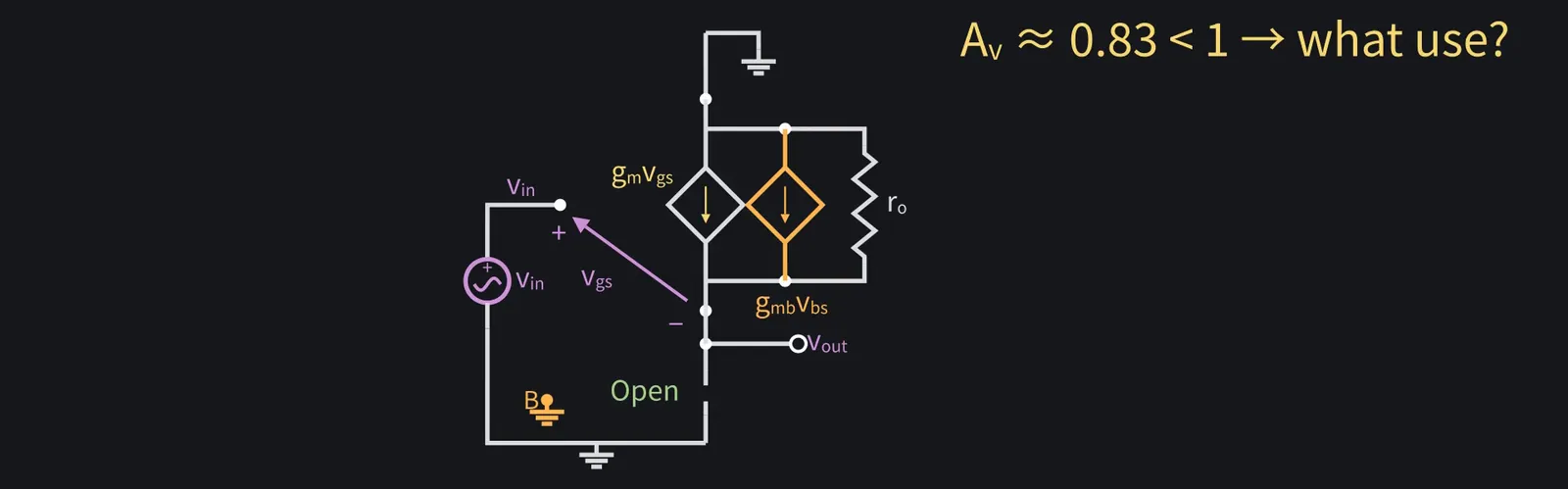
Illustration: What use is a stage with gain below one?
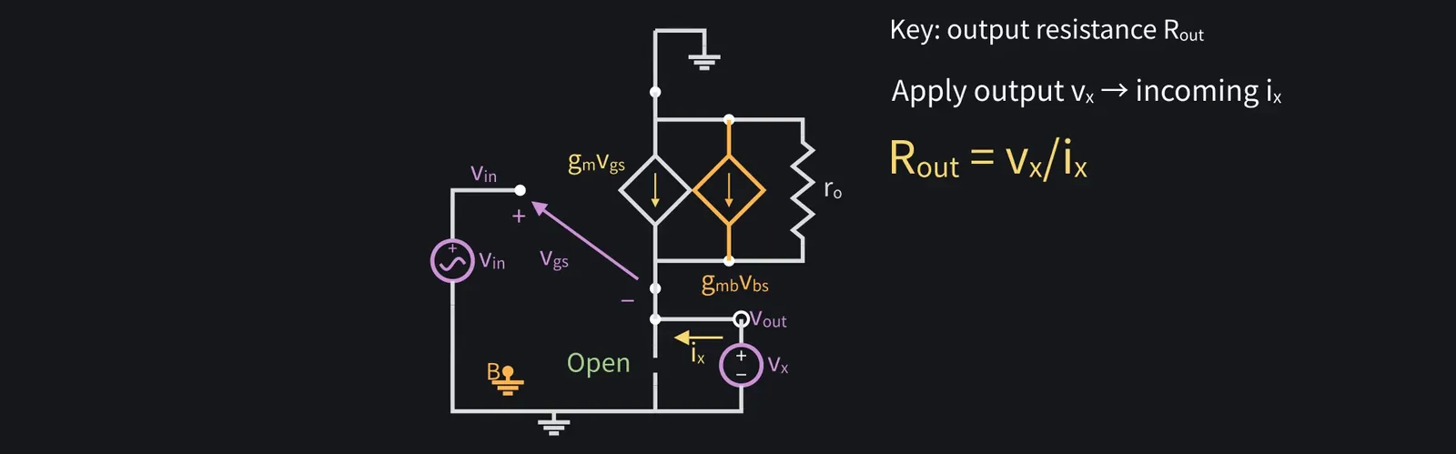
Figure 22

Shikoku Metan

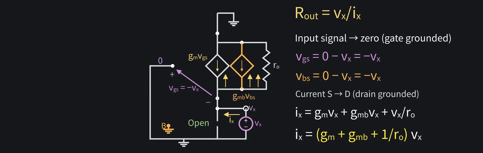
The key is output resistance. Apply a test voltage vx at the output and find the current ix flowing in.

Illustration: The key is output resistance. Apply a test voltage vx at the output and find the current ix flowing in.
Figure 23

Shikoku Metan

Set the input signal to zero. The gate and body are then at ground while the source is at vx, so vgs and vbs both equal −vx.

Shikoku Metan: Adding the two current sources and the current in ro gives ix = (gm+gmb+1/ro)vx. The current is proportional to vx, and the coefficient is the same as the gain's denominator.

Illustration: Adding the two current sources and the current in ro gives ix = (gm + gmb + 1/ro)vx. The current is proportional to vx, and the coefficient is the same as the gain's denominator.
Figure 24

Zundamon

A current source behaving like a resistor!
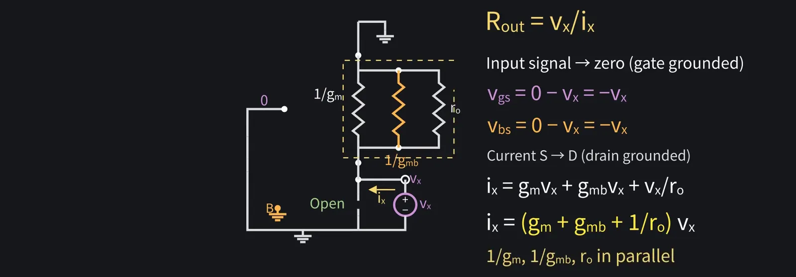
Illustration: A current source behaving like a resistor!
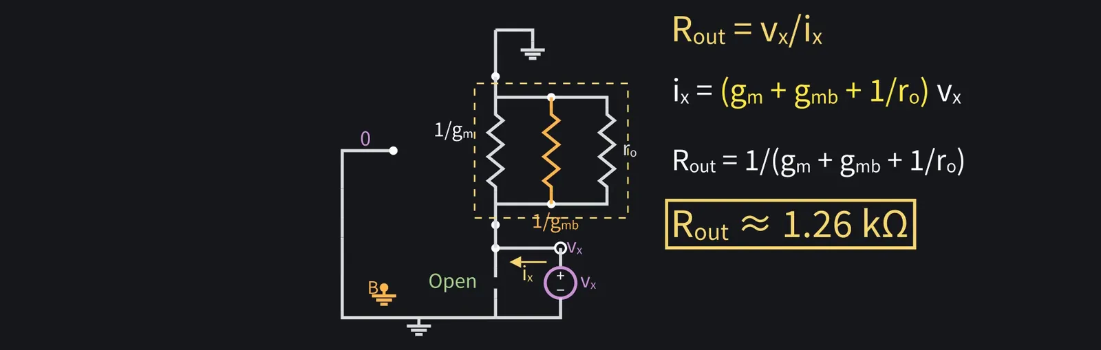
Figure 25

Shikoku Metan

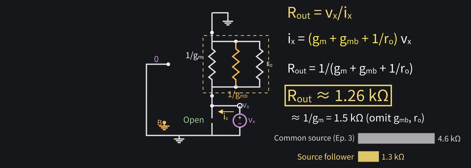
Right. The inverse gives Rout≈1.3 kΩ, including body effect.

Illustration: Right. The inverse gives Rout ≈ 1.3 kΩ, including body effect.
Figure 26

Shikoku Metan

Ignoring gmb and ro gives the handy estimate Rout≈1/gm, about 1.5 kΩ.

Shikoku Metan: Much smaller than episode three's common-source output resistance of 4.6 kΩ.

Illustration: Much smaller than episode three's common-source output resistance of 4.6 kΩ.
Figure 27

6The role of a buffer

ZundamonQuestion

Why is lower output resistance useful?

Illustration: Why is lower output resistance useful?
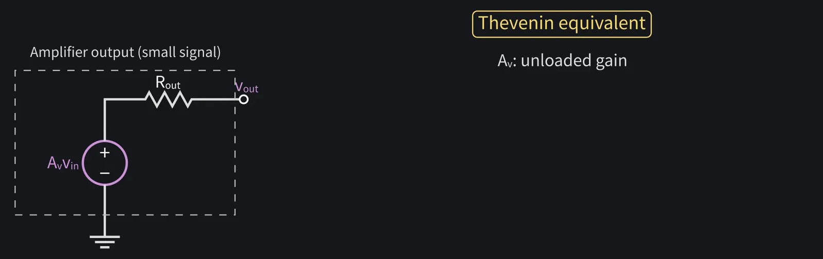
Figure 28

Shikoku Metan

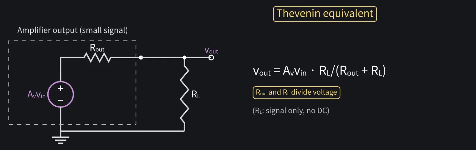
For small signals, an amplifier's output can be modeled as a voltage source Av·vin in series with Rout: the Thévenin equivalent from circuit theory.

Illustration: For small signals, an amplifier's output can be modeled as a voltage source Av·vin in series with Rout: the Thévenin equivalent from circuit theory.
Figure 29

Shikoku Metan

Connect a load RL that carries only the signal and no DC (say, through a coupling capacitor), and the output is divided between Rout and RL.

Illustration: Connect a load RL that carries only the signal and no DC (say, through a coupling capacitor), and the output is divided between Rout and RL.
Figure 30

Shikoku Metan

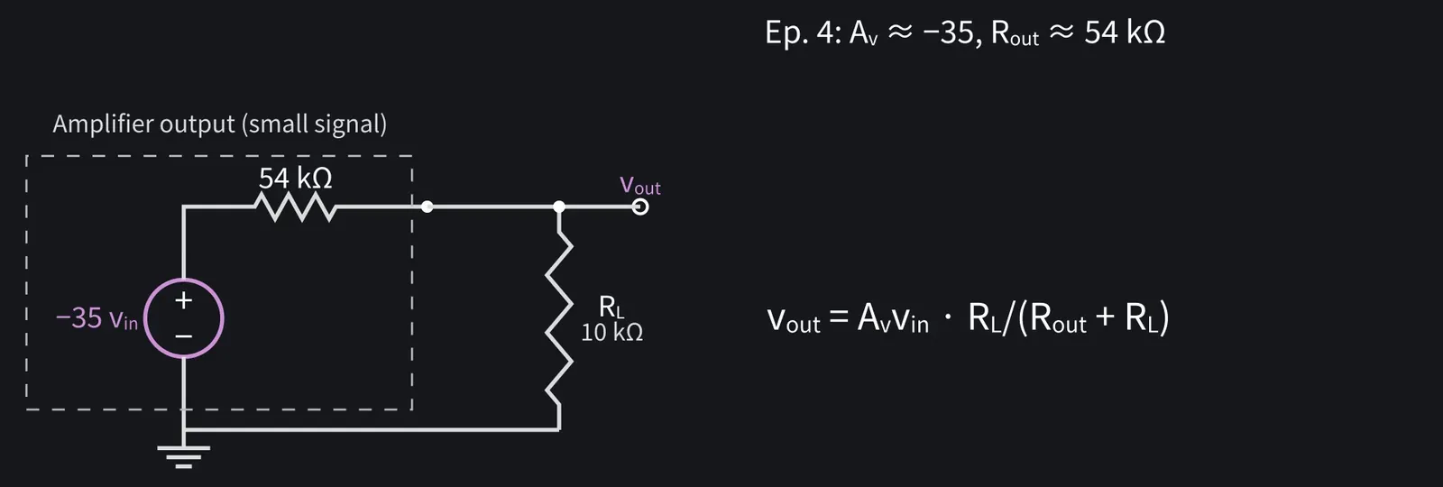
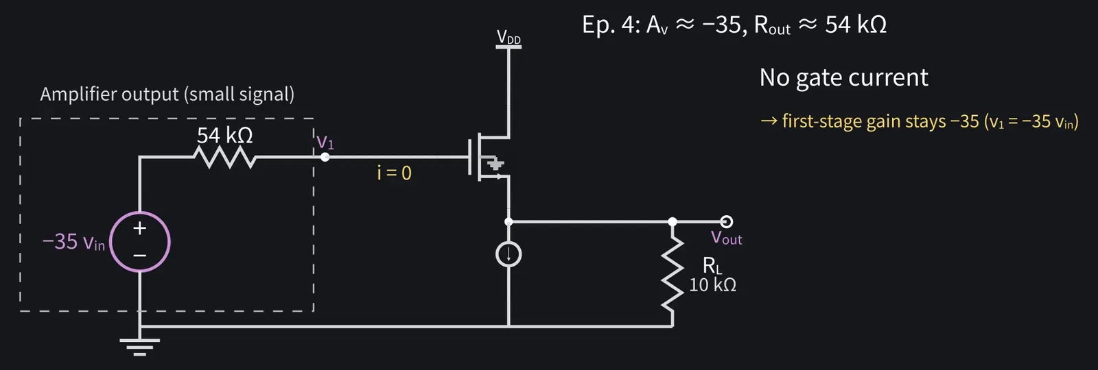
Episode four had gain −35 and Rout≈54 kΩ. Add RL=10 kΩ...

Illustration: Episode four had gain −35 and Rout ≈ 54 kΩ. Add RL = 10 kΩ...
Figure 31

Zundamon

−35×10/(54+10): the gain drops to about −5.5! Just like my experiment, nanoda!
Shikoku Metan

Insert a source follower. Its gate draws no current, preserving the first stage's gain.

Illustration: Insert a source follower. Its gate draws no current, preserving the first stage's gain.
Figure 32

Shikoku Metan

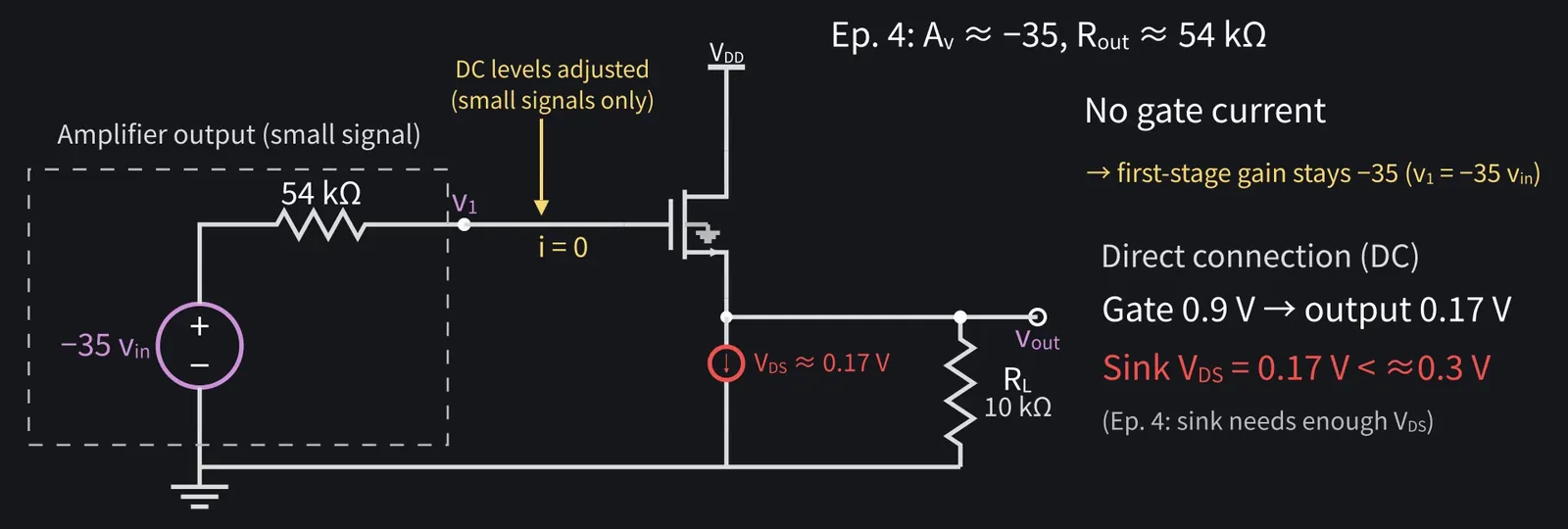
Assume the DC levels between stages are adjusted, and consider only small signals.

Shikoku Metan: The previous stage's output sits at about 0.9 V DC. Connected directly, the follower output would be about 0.17 V, below the roughly 0.3 V the current sink needs to stay in saturation.

Illustration: The previous stage's output sits at about 0.9 V DC. Connected directly, the follower output would be about 0.17 V, below the roughly 0.3 V the current sink needs to stay in saturation.
Figure 33

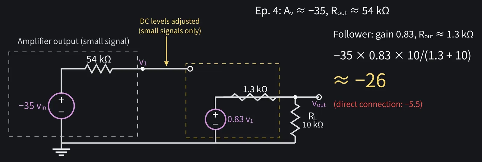
Shikoku Metan

The follower's Rout is about 1.3 kΩ. −35×0.83×10/(1.3+10) gives an overall gain of about −26.

Illustration: The follower's Rout is about 1.3 kΩ. −35 × 0.83 × 10/(1.3 + 10) gives an overall gain of about −26.
Figure 34

Shikoku Metan

A stage that drives the load this way is a buffer: a key role for the follower.

7The common-gate stage

Shikoku Metan

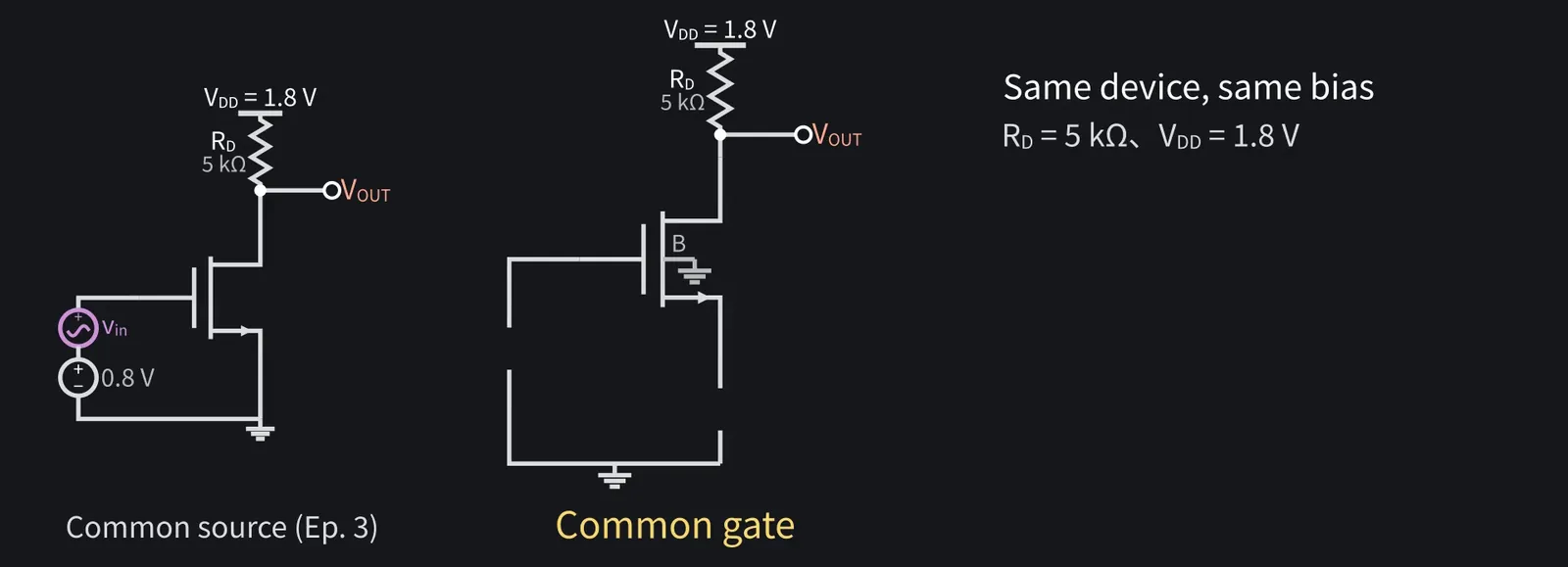
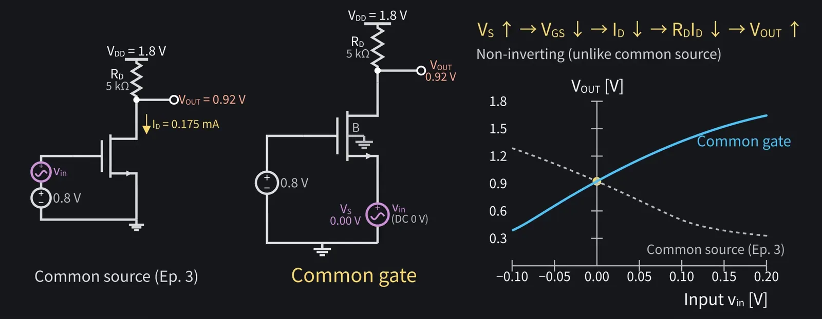
Third, common gate. Use the same device and bias as episode three for comparison.

Illustration: Third, common gate. Use the same device and bias as episode three for comparison.
Figure 35

Shikoku Metan

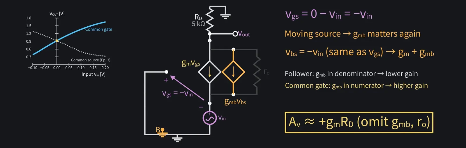
Fix the gate at 0.8 V DC, apply vin at the source, and take output at the drain.

Shikoku Metan: Source DC is zero, so the bias is unchanged: VOUT≈0.92 V.

ZundamonQuestion

If the source voltage rises, what happens to the output?
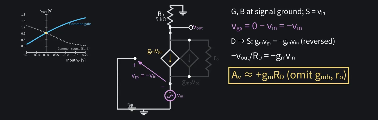
Shikoku Metan

VGS and current fall, so VOUT rises. Unlike common source, it doesn't invert.

Illustration: VGS and current fall, so VOUT rises. Unlike common source, it doesn't invert.
Figure 36

Shikoku Metan

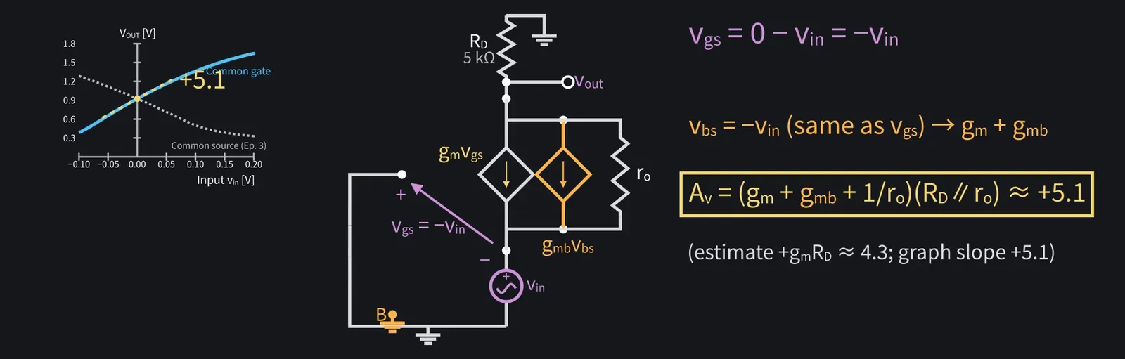
For small signals, vgs=0−vin = −vin. Ignoring body effect and ro, Av = +gm·RD.

Illustration: For small signals, vgs = 0 − vin = −vin. Ignoring body effect and ro, Av = +gm·RD.
Figure 37

Shikoku Metan

The source moves here too, so gmb comes in. vbs is −vin, the same as vgs, so this time gmb adds to gm and raises the gain.

Illustration: The source moves here too, so gmb comes in. vbs is −vin, the same as vgs, so this time gmb adds to gm and raises the gain.
Figure 38

Shikoku Metan

Including ro, Av = (gm+gmb+1/ro)(RD∥ro) ≈ +5.1.

Illustration: Including ro, Av = (gm + gmb + 1/ro)(RD∥ro) ≈ +5.1.
Figure 39

ZundamonQuestion

Does current flow into a source input?
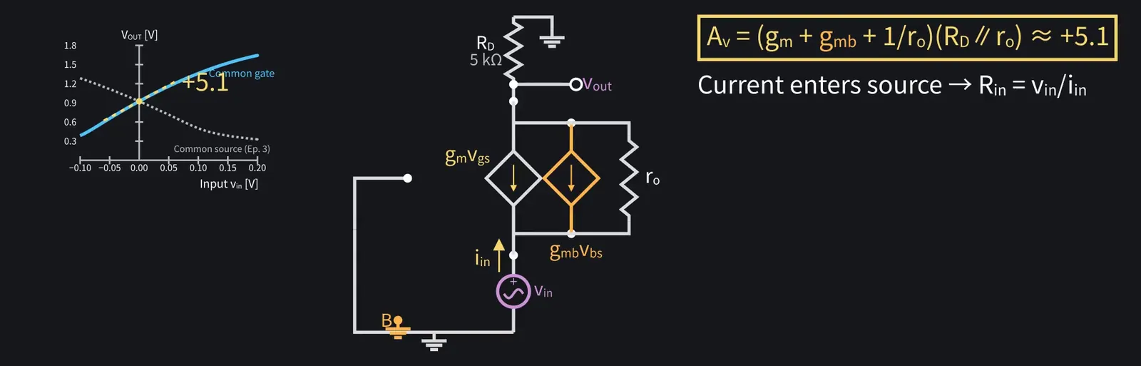
Illustration: Does current flow into a source input?
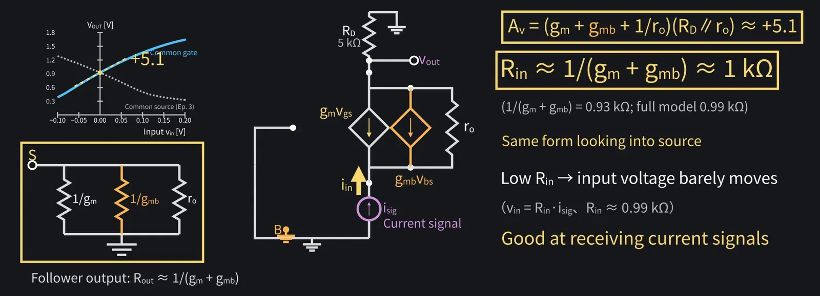
Figure 40

Shikoku Metan

Yes. Rin≈1/(gm+gmb), about 1 kΩ: the same form as the follower's Rout.

Shikoku Metan: Its low input resistance makes it good at receiving signals supplied as currents.

Illustration: Its low input resistance makes it good at receiving signals supplied as currents.
Figure 41

Shikoku Metan

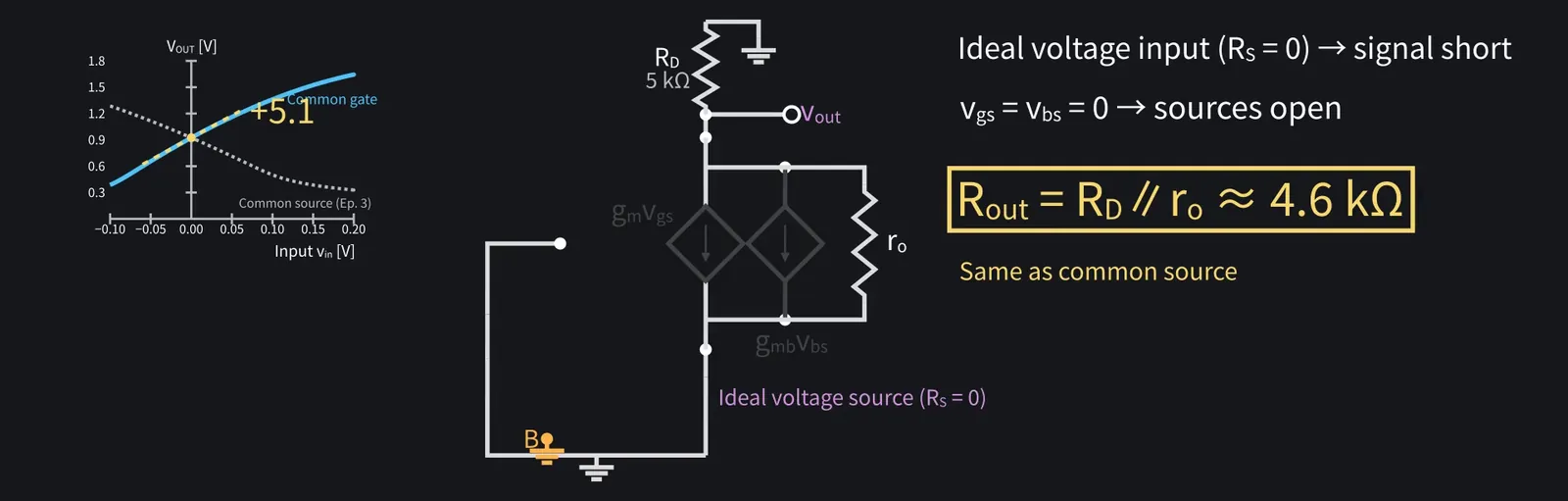
With an ideal voltage-source input, Rout=RD∥ro≈4.6 kΩ, like common source.

Illustration: With an ideal voltage-source input, Rout = RD∥ro ≈ 4.6 kΩ, like common source.
Figure 42

8Comparing the three basic amplifiers
Shikoku Metan

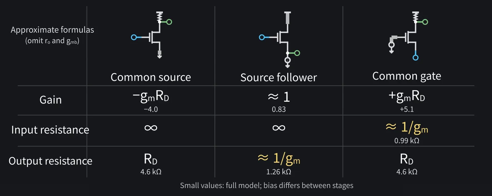
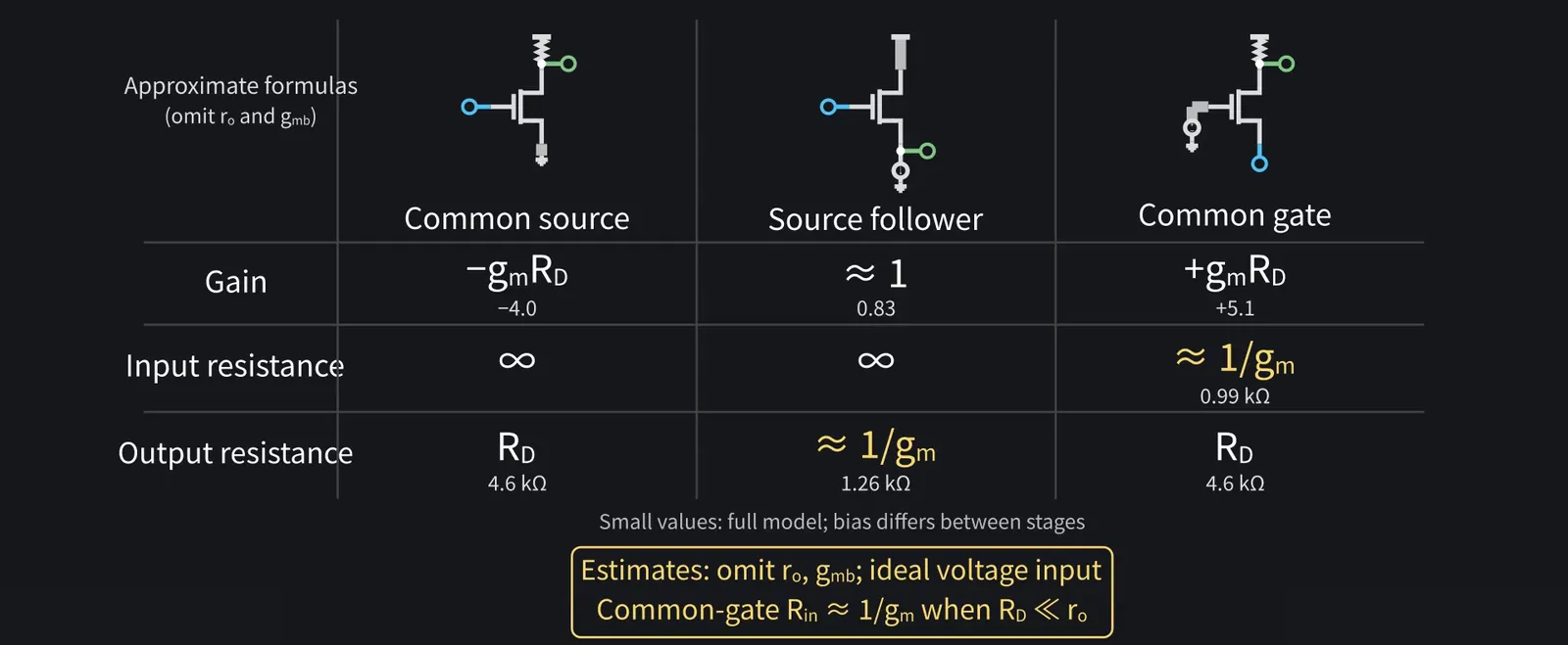
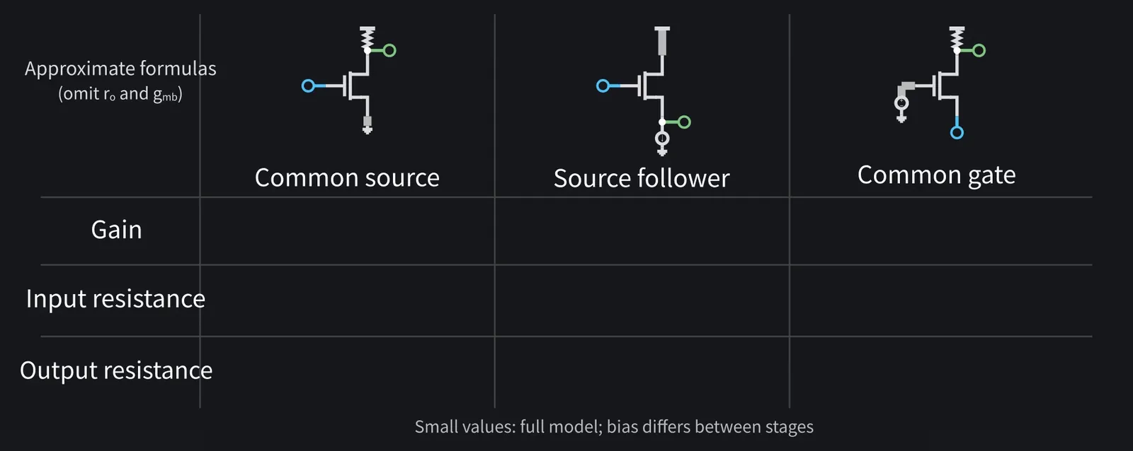
Let's summarize with approximate formulas, omitting ro and gmb.

Illustration: Let's summarize with approximate formulas, omitting ro and gmb.
Figure 43

Shikoku Metan

Gain: common source −gm·RD, common gate +gm·RD, source follower about one.

Shikoku Metan: Input resistance: infinite at the two gate inputs; about 1/gm for common gate.

Shikoku Metan: Output resistance: RD at drain outputs, about 1/gm for the source follower.

Illustration: Output resistance: RD at drain outputs, about 1/gm for the source follower.
Figure 44

Zundamon

Whenever the source is input or output, 1/gm appears!
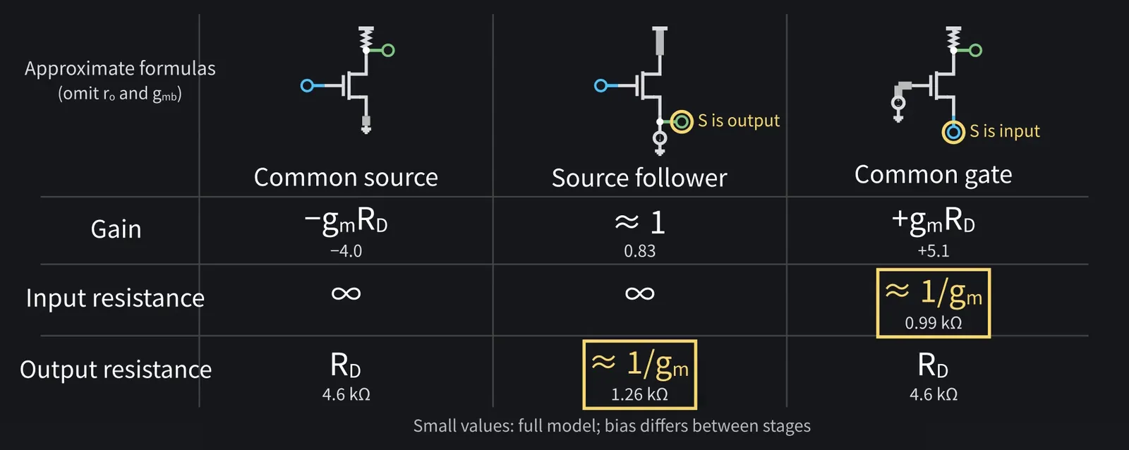
Illustration: Whenever the source is input or output, 1/gm appears!
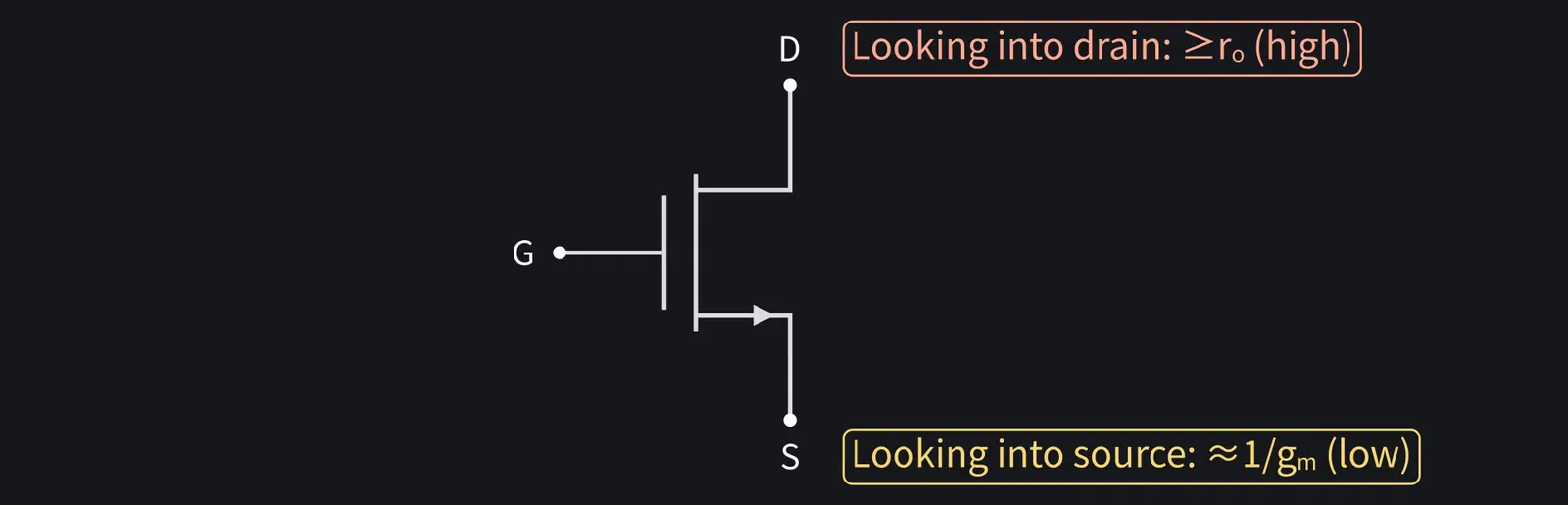
Figure 45

Shikoku Metan

A useful rule: low resistance looking into the source, high looking into the drain.

Illustration: A useful rule: low resistance looking into the source, high looking into the drain.
Figure 46

Shikoku Metan

These estimates depend on what connects to the other terminals. That will be the key next time.

Illustration: These estimates depend on what connects to the other terminals. That will be the key next time.
Figure 47

9Summary

Shikoku Metan

A source follower is a buffer with gain near one and output resistance about 1/gm.

Illustration: A source follower is a buffer with gain near one and output resistance about 1/gm.
Figure 48

Shikoku Metan

Body effect lowers the gain a little further below one.

Zundamon

Common gate has Rin≈1/gm and gain ≈ +gm·RD, nanoda!
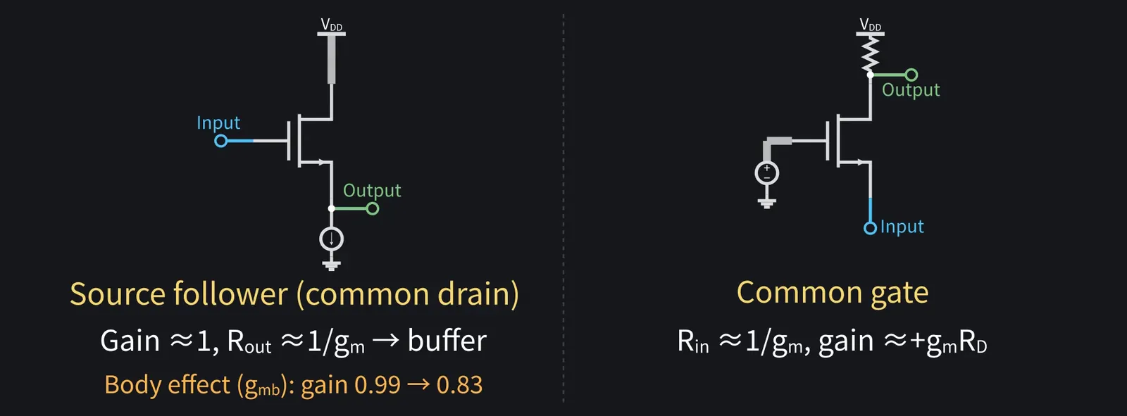
Illustration: Common gate has Rin ≈ 1/gm and gain ≈ +gm·RD, nanoda!
Figure 49

Zundamon

Now I can explain loading and buffers in my lab report!

Shikoku Metan

Next time: stack common gate on common source for a cascode with higher Rout.

Illustration: Next time: stack common gate on common source for a cascode with higher Rout.
Figure 50

Zundamon

Thanks for reading, nanoda!